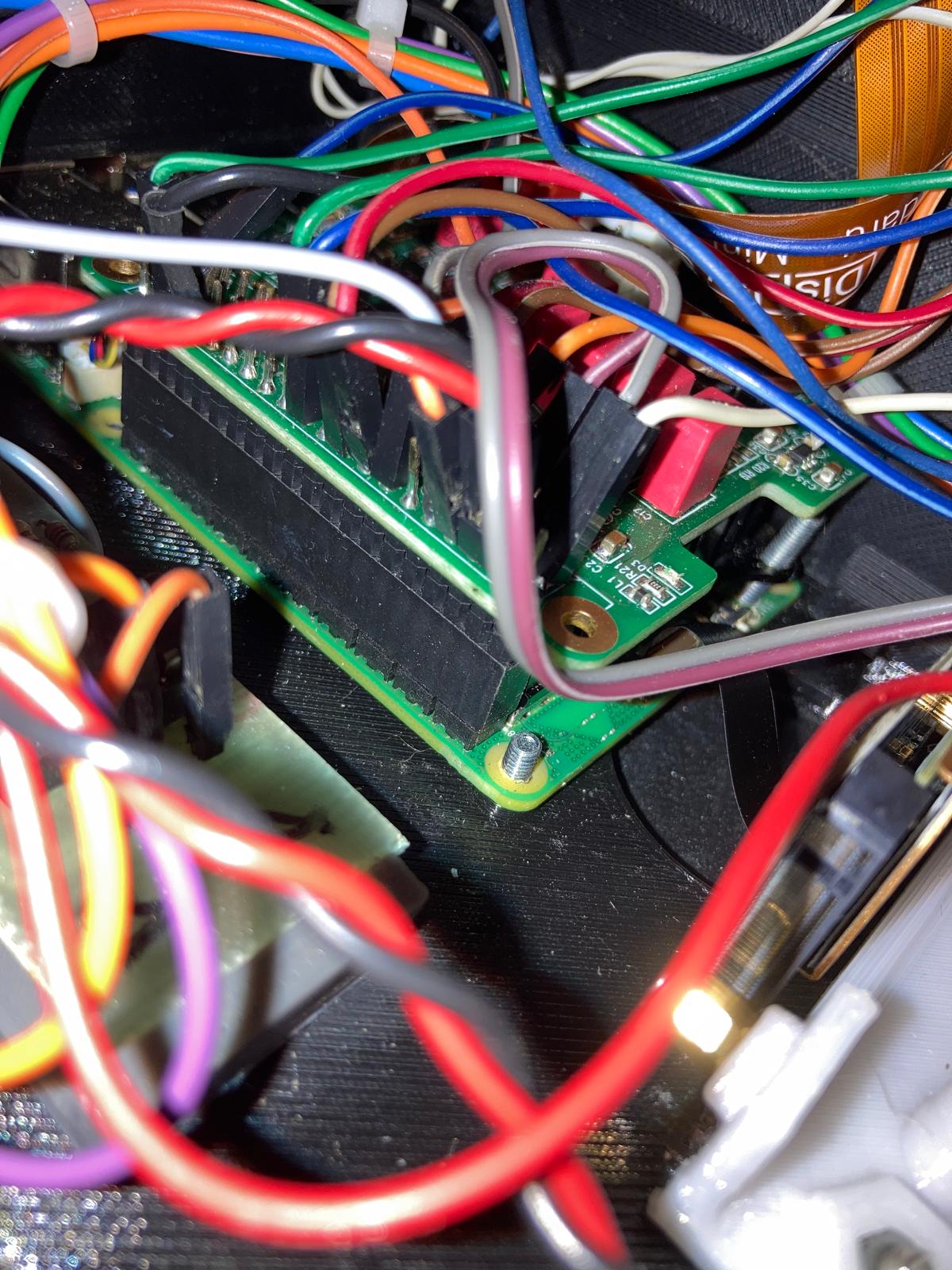
@hannesmenzel I apologize if I didn’t understand well, my English is terrible and Google translator is worse than me. If you insert the audio card into the Gpio, the card itself has a Gpio extension to which you can connect the encoders. You don’t have to solder anything. I put the image of my Zynthian. If I understood badly I apologize.
As far as I know in the Hifiberry Dac2* the RCA connectors and the analog balanced pin connectors are already in parallel. So the question would be, if I couldn’t also connect the output pins to both the output jacks and the headphone amp in parallel. I might or might not take care of using just one of these at a given time. I maybe could also use switchable jacks so that the outputs are only connected if a cable is plugged in. I couldn’t switch the headphone amp off by unplugging the cable obviously.
I also didn’t find a solution how to use switchable jacks to have a either-or use of output or headphone amp. I can imagine a setup where the headphone amp’s input only gets connected when the output cables are plugged in, but obviously the intended behaviour would be the exact opposite.
So can anybody elaborate if there would be a problem in doing this:
- Hifiberry analog output connectors to output jacks
- Output jacks directly to TPA6112 hp amp
- Hifiberry 5V out to TPA6112 hp amp
- TPA6112 hp amp out to HP jack
- All jack connectors to GND when given cable is unplugged.
Indeed the next problen will be where to find the mentioned amplifier. If you know a model currently available, potentially even from a EU based supplier, I would be greatful.
No problem with it.
The one thing I would add is a separate headphone volume control.
You could do that with a stereo log law 10k pot between your Hifiberry Outputs and the TPA6112 input.
An easy alternative to the TPA6112 route is a USB headphone output, because with USB hotplug this can be implemented from within the Mixer, removing the need for the separate control.
The case you’re describing assumes that I used the RCA output and only connecting the hp amp to the hifiberry analog pinouts. I thought about connecting like described abobe:
Still no problem?
If you’re in Germany, this link may be helpful
3 is not too many ![]()
Another alternative for a headphone amp, with a schematic under creative commons and using two op-amps to achieve high power:
1 Like
Hi there,
I now ordered that thing here.
I also asked in the HifiBerry forum, they answered quite fast and confirmed it should work like that, maybe with some low frequency response issues.
Now there are some questions left:
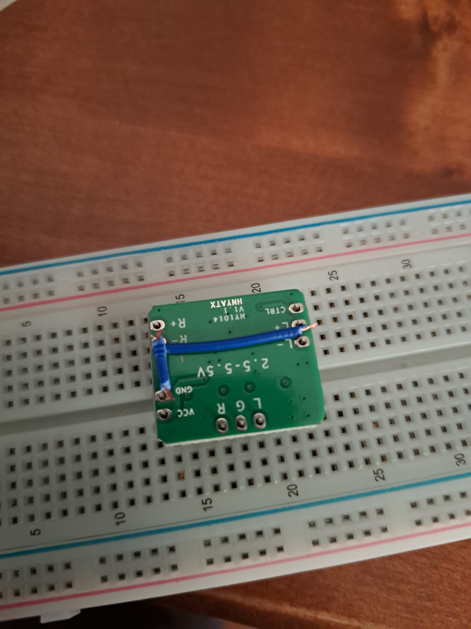
Can anybody explain why OP used the L- and R- for signal and connected R+ and L+ to ground? I’m aware that it is to abandon the non existent inverted signal from a balanced out. From my understanding it should not be a huge problem, but I thought the negative line is supposed to be fed by an inverted signal (which is not the case for a dac board with unbalanced out though). I would have connected just the + to signal and the - to ground.
I also ask myself if connected in parallel like planned if plugging or unplugging any of the two possibilities would make some noise on the other output.
Also, do you know what the low frequency issue mentioned in the Hifiberry community be addressed by?
I don’t know why anyone would suggest connecting it that way. Zynthian official hardware has outputs that can be configured as differential (balanced) or single-ended. It is normal to use tip as hot, ring as cold and sleeve as ground. If you wired this with all three connected, i.e. hot to hot, cold to cold and ground to ground, then configuring zynthian as single ended or balanced should still work.
1 Like
Yes, but my DAC2 ADC Pro just has unbalanced out (as you pointed out after my 5V-to-audiojacks-incident), and the HP-amp in question has balanced in. It totally makes sense to me to ground one of the amp input pair, but I thought the L- and R- would be the most suitable pair to ground. Probably it doesn’t affect the outcome at all anyway.
So in fact when the board arrives I’d plan to connect it like this: Since I already have 1/4" unswitched output jacks connected (originally balanced but soldered - to GND) to the Hifiberry analog outs I think I’ll just solder another wire from the output jacks to the HP amp L+ and R+ respectively and then I just connect the Hifiberry 5V out (or GPIO-V+pin 4) to VCC and many wires from Hifiberry GND to HP amp GND, L-, R- altogether. Then I just use another (unswitched) stereo output jack witch TRS → LRG.
And then I do what I always done the last month: switch on an hope it will not blow up.
2 Likes
Sorry to bother you again. This thing finally arrived.
I want to start, but since the original instruction on top seems to work for some of you I have to be sure:
I already mentioned my doubts about connect the amps L+/R+ to DACs GND, but that might work with unbalanced out. But also it says literally to connect the DAC cold signal (which I haven’t, or what on earth is 5V- opposed to GND?) to the amps GND. Everything of it confuses me.
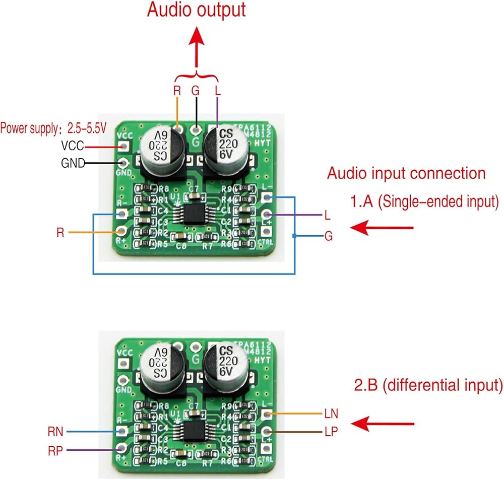
For me it is logical to connect DAC 5V and GND to amp VCC and GND. Then amps L-/R- (and maybe CTRL) also to GND. Then unbal. signal to L+/R+.
This also complies with the descriptive image from the products amazon offer:
Please be patient with me, with my clumsy fingers its irreversible after I turn on the soldering iron.
So I just did it. And it produces output on both the analog out and the headphones. With the latter it’s true that it lacks a bit of both low end and high end I would say. And I need to turn down the output level to 60/100 on headphones, but that was clear.
1 Like
I wonder why one would like to add another crook to an already failed design?
These low-power “amps”, be it the TDA onboard the V5.x or the chinese thing, deliver reasonable sound only for low-Ohm headphones between 16 and 32 Ohm. The usual range for Hi-Fi or studio headphones is 300 to 600 Ohm.
This is incompatible by design.
I’d design a REAL headphone amp with some matched pairs of trannies or at least some NE5532, if it has to be made with ICs. For this, a higher voltage is needed, wich is available from the power supply via a separate filter and low noise linear regulator, or from even as low as 5V via an isolated bipolar DC-DC converter with adequate filtering (the solution I prefer, because it allows real ground-referenced DC-coupled output to be designed).
If here is interest, I’d make something for the purpose, maybe for the next HW version as well?
1 Like
I’d be interested in whether you think the schematic below-above, available under a Creative Commons license, would do the job, or what you’d do differently. It uses a pair of op-amps for each channel. Do you think a pair of discrete transistors would be better?
Better, maybe. More difficult to make well, absolutely.
The schematic of the HC1 you mentioned is simple and easy to fabricate, so go for it.
For the Power supply from the 5V rail I’d suggest Murata NMH0509DC 5V to +/-9V 2W dual converter and on both output rails 47µH 2.2µF LowESR and 47nF ceramic LC-filtering plus then RC filtering via two 82Ω (minimum 10Ω) resistors and the 220µF LowESR of the schematic, put 0.1µF ceramic in parallel as well and connect middle output to headphone ground. That would make a nice PS and leave out the unavoidable ripple, which is in the 90kHz range, anyway. A bit of adjustable HF negative feedback would eliminate any remains of the noise, but would require fine tuning and may not be necessary.
This way you get a whopping headphone driver suitable for anything between 16Ω and 1200Ω.
btw: the 50 hours on a 9V battery shown on the shopping page may be true, but only with silent output. In reality, these drain much earlier, maybe in 6 hours or so.
EDIT: Maybe the converter does take too much time to start with the two 10Ω resistors, due to the high capacitive load, so something up to 82Ω may be necessary, or simply use 82Ω in the beginning. The 220µF will stabilise the power rail, anyway.
It is important to place the LED and the voltage divider resistors as some sort of a base load, or otherwise the converter may flip it up to +/-18V, which approaches the +/-22V absolute maximum rating of the NE5532.
1 Like
Thanks for the advice and tips @fussl !