Hi, I’m trying to build my DIY Zynthian to integrate it on my Ableton set up to save some CPU with synth sounds.
I’ve this encoders and want to know if I could use it with wires direct to the GPIO and avoid to use other PCB or Arduino.
I’m working now with a usb audio card uca202 (configured on web like the 222 and works fine)
My display is a 7" with the HDMI and USB port working fine too.
Working with Ip midi on OS X connected to a switch and no latency on Ableton Live.
If I can put the encoders directly will make some wood case for all.
Can I also connect directly too a female midi port?
Sure! The original Zynthian has encoders wired directly to the Raspberry Pi header and this is still supported on the firmware and configuration.
This old guide includes some clues but basically you need to wire pins of the encoders to spare GPIO pins on the RPi header then select, “Prototype 1” in webconf and give the pin numbers used on RPi header as comma separated list in each field. (I think it is Prototype 1 but maybe it is custom.)
Regarding MIDI port, the Zynthian supports hardware MIDI input and output but needs a few components to interface. You could build this yourself or buy an interface board but if you are spending money on such toys then maybe the official parts.
Yes, I’ve got several machines wired up in all kinds of strange configurations and whilst you quickly forget the difficulties of the configuration on a home built ( There’s many, many pages illustrating various examples) I would strongly suggest getting the ‘official’ interfaces as these have been heavily tested both before release and in the wider community.
I should be playing music, I actually spend far more time trying to keep long distance I2C connectors alive which is entirely my own fault !
Thanks all, i’ve some encoders because I’m making a midi controller with arduino and encoders and ring rgb Leds to work with Ableton. So I just use it and go to complete The zynthian to go deep on it. Tomorrow will try it.
Thanks for the support guys. <3
Those encoders have pull-up resistors hence a connection for +V. I don’t think these are needed as RPi can use internal weak pull-up but there should be no harm connecting it to 3.3V (not 5V). You may have an issue with switch bounce. The Zynthian encoder circuit used hardware switch debounce (using some small capacitors).
Sorry for all the cuestions :S
On the webconfig " MCP23017 INT-A Pin: and MCP23017 INT-B Pin: " I need to put default if I don’t have one? And this pins will be on the " Encoders A-pins: and Encoders B-pins:" right?
EDIT
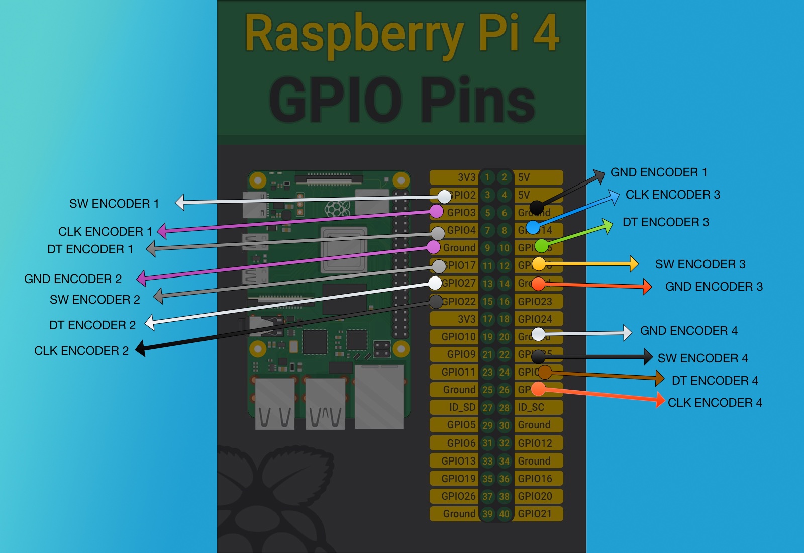
I wired it and make Prototipe 1 config like this:
Encoders A-pins: 3,4,15,18
Encoders B-pins: 17,27,25,8
Switch pins: 2,14,22,7
The other MCP default and the last empty.
Only works the 1st encoder down and the clk
I’m so confused. Which correspond to clk and which to DT on my key-040 . I need to find this to wire all like you do and see if works.
So complicated this gpio thing.
These rotary encoders use a quadrature encoding. In their rest state both signal pins are disconnected. As you turn the shaft, the common (ground) pin is first connected to one signal pin, then both pins then the first signal pin is disconnected and finally both are disconnected as you return back to a detent. The Zynthian decodes this to detect direction and rotation, one detent at a time. The “Clk” and “DT” pins are actually just these two signal pins. As long as you connect ground to the common pin and each signal pin to a GPIO then assign the pins in the webconf it should work. It is possible that it will work in reverse if the pins are reversed but that is simply resolved by reversing the configuration in the webconf. The switch is activated when the shaft is pressed connecting. This needs ground on one side and a GPIO on the other.
Checkout the link that @wyleu posted. He has made this work.
Yes. THe major confusion is the Numbers we refer to from within the webconf display.
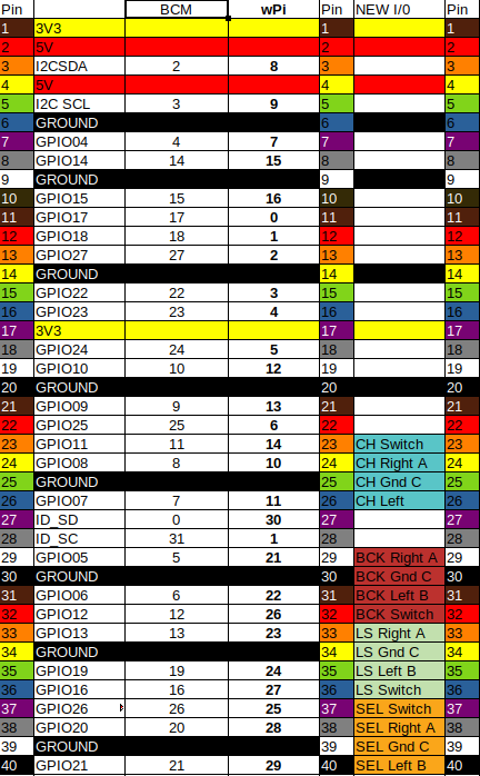
This is the webconf of the machine (zynthian-ceed.local) using the wiring described. It’s my dev machine which gets all kinds of abuse.
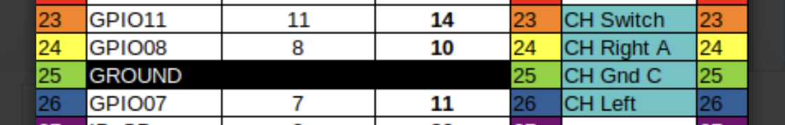
As you can see it refers to pins and the interrupts. but these numbers refer to BCM column in the chart which then need mapping across to the PIN’s on the GPIO connector.
This is done because these are the pins on the main raspberry Pi chip BCM (something or other) which is the real target of software, this way we could move zynth outside of the Raspberry Pi should it be required. Much more flexible!
Course the Raspberry IO pin connector is a standard that has been adopted all over the place so it all gets more confused. But If I wanted to use the chip to make my own machine without an IO connector I could and that’s why software writers do it this way.
It does work!
Here’s the advantage of all this mucking around. As you can see in this machine space is very tight and laying the ribbon cables like this it allow it all to be assembled. I can then use the mapping to just choose the relevant pins on the PI that these connect to. Software flexibility saves space in the box !!


 .
.
 . I need to find this to wire all like you do and see if works.
