Got it up and running using resistive PiTFT 2.8 and internal pi 3 audio (no encoders). I was hoping to use the 4 switches on the PiTFT. They connect to the Pi GPIO pins 17,22,23,27 directly but when I put those values into the switches pins and set the custom switch actions it doesn’t work. Any clues?
Hi @utensil. Welcome to the community. I hope you enjoy it here and have fun with your new Zynthian.
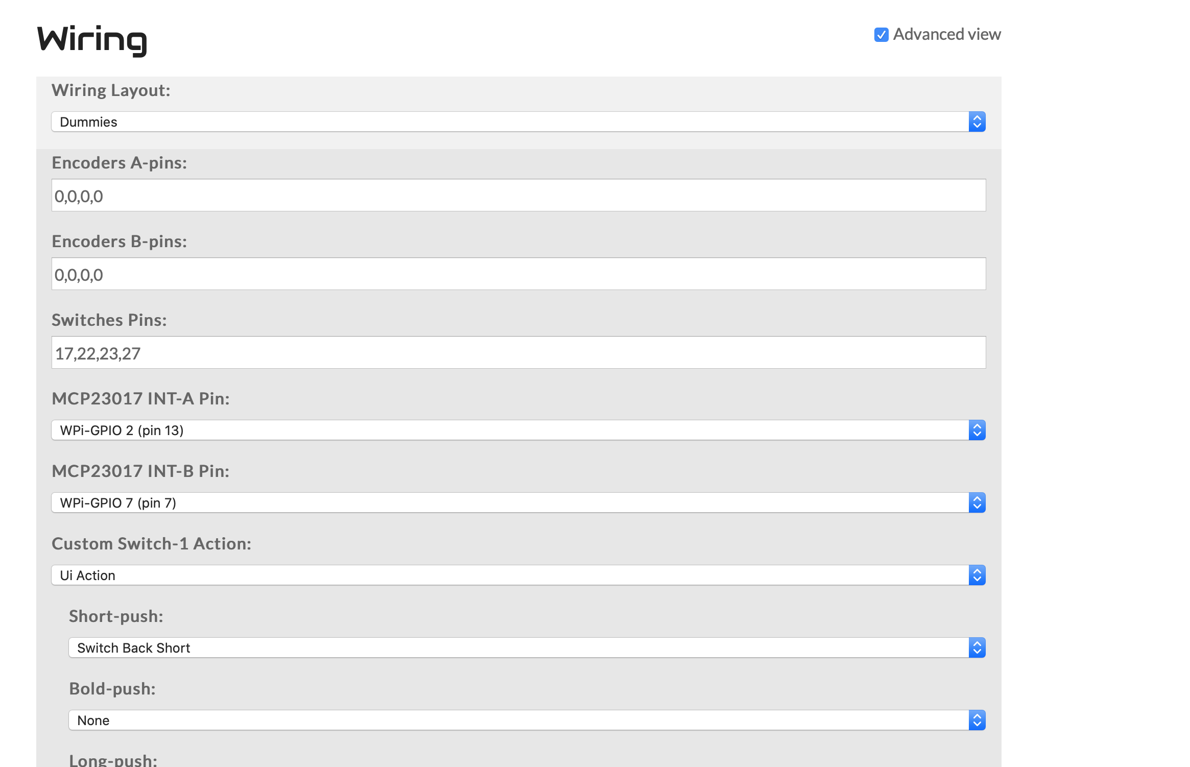
Your screenshot shows you have “Dummies” wiring layout selected. This disables the switches and encoders so the other parameters in the webconf screen are irrelevant. I think you need to select “Custom” as the wiring layout.
Good luck and please report back on your success. 
Thanks, Ok so after much trying, I’ve managed to get 3 of the 4 switches working.
I have verified (with multimeter) that the switches (marked #17,#22,#23,#27) physically map to the PI 3’s pin 11 (GPIO 17), pin 15 (GPIO 22) , pin 16 (GPIO 23) and pin 13 (GPIO 27)
That all seems sensible but oddly…
It seems in the Zynthian settings switches #22,#23 and #27 are mapped to Zynthian named pins (3,4,2) respectively. I have not found any pin to match the switch marked #17.
Also I need to put the switch pins as 0,0,0,0 before the 4 custom switches I want to add. right now I have it as 0,0,0,0,0, 3,4,2 (see attached). The fifth 0 needs to be replaced with the pin for switched marked #17 (I’ve tried everything from 1-40). Also it doesn’t make a difference if I set it to custom or dummies as long as encoder A-pins and encoder B-pins are set to 0,0,0,0
It’s bizarre behavior so I’ve probably missed understanding something somewhere. Anyone can make sense of this??

The pin numbering on the Pi is a little bit confusing cos There are two ways of describing the pins BOARD or BCM …
One is the pins on the raspberry PI GPIO connector
The other is viewed from the Broadcom chip pins
Code kind of favours the second cos it means the code is more portable whilst us users of soldering irons tend to prefer the board approach.
The listing in the webconf is based around the BCM pins which in our world correspond to the Wpi pins in the table below…
I cant at the moment remember why there is another mapping, but these are he numbers that work !!
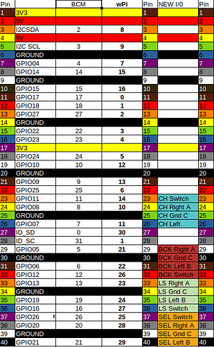
So you need to match the pins of the GPIO connector with the WPi numbers to find out what goes in webconf. . .
You should see that your GPIO i/o match up against the wPI pins…
In the webconf world pin numbers over 100 are involved with 12C connected devices like allinone boards and such like
1 Like
Amazing, Thanks bro. It looks like GPIO #17 is pin 0. will mess around and try it out and report back. Thanks
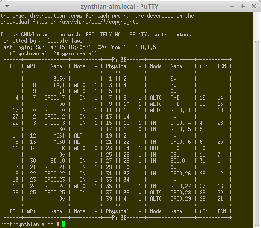
there is also gpio readall … ( can’t remember if you need to install anything for this but it tells you whats going on . . . .
OK super helpful but still can’t get switch #17 (pin 0 per the mapping u updated). If I leave encoder A & B pins blank and just put in the 4 switch pins (0,3,4,2) , the #17 pin still doesn’t work , the other 3 respond but not per the action I set. Also the touch screen doesn’t respond.
The best result I’ve gotten so far is to put
0,0,0,0 in encoder A & B pins and 0,0,0,0,0,3,4,2 but #17 (pin 0) switch still doesn’t work.
Without tearing into the code I do wonder if the 5 0’s might be an issue.
Could you try another Pin that doesn’t use that 0 value?
Cn you log onto the zynth from another machine ?
gpio readall
will actually show you the detected signal and the i/0 direction of the individual pins. That will, at least, tell you that the pin can be read.
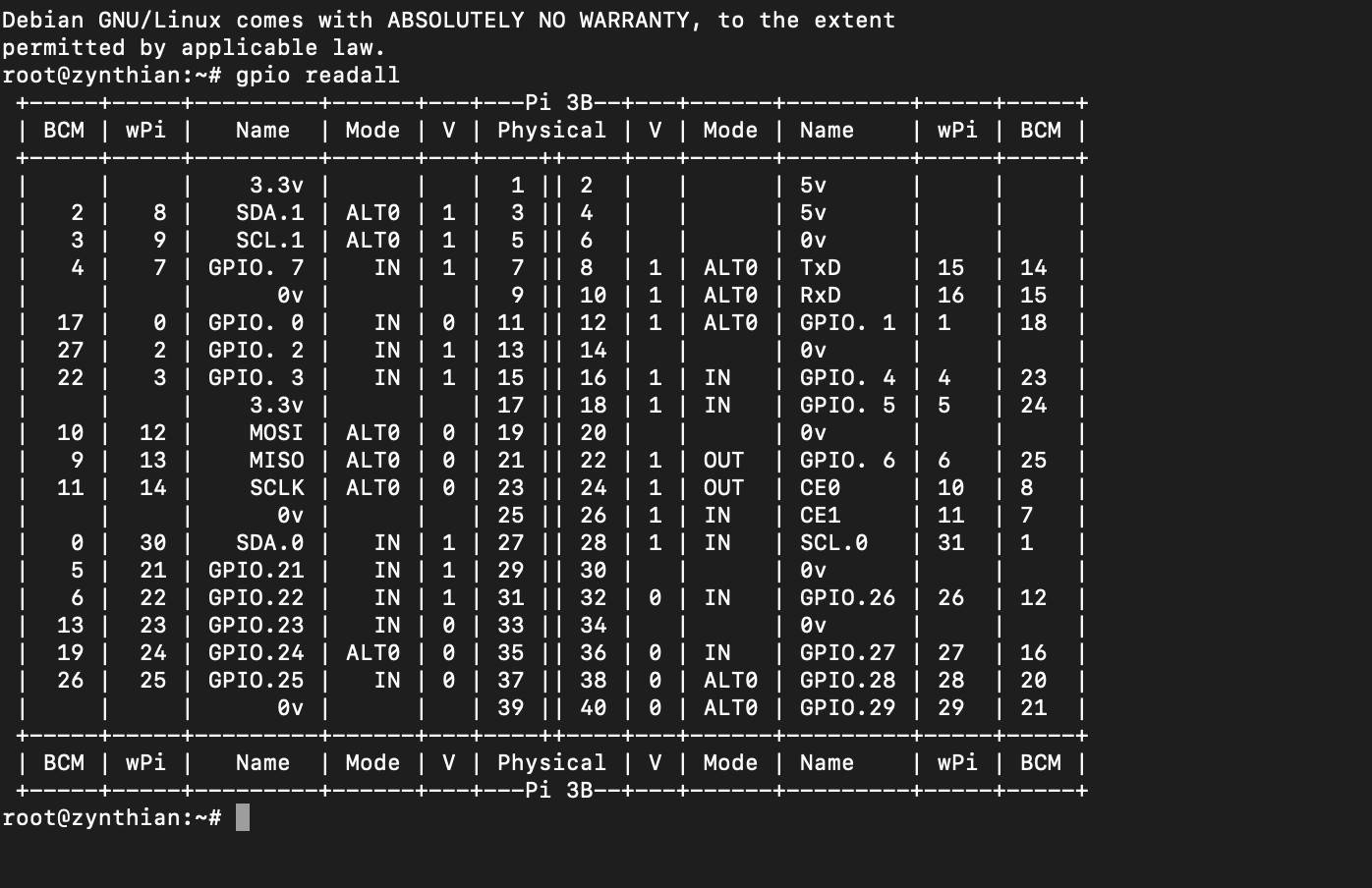
Thats what I get back, 17 seems to be mapped to 0, but it’s probably that I’ve entered 0,0,0,0 as the dummy encoder values but If I leave it blank I get erratic behavior

Got it , more than helpful, will update once I figure this sh*t out