If you, like me make 40 pin connectors for use with zynths then tend to believe them to be the villain before your own soldering.
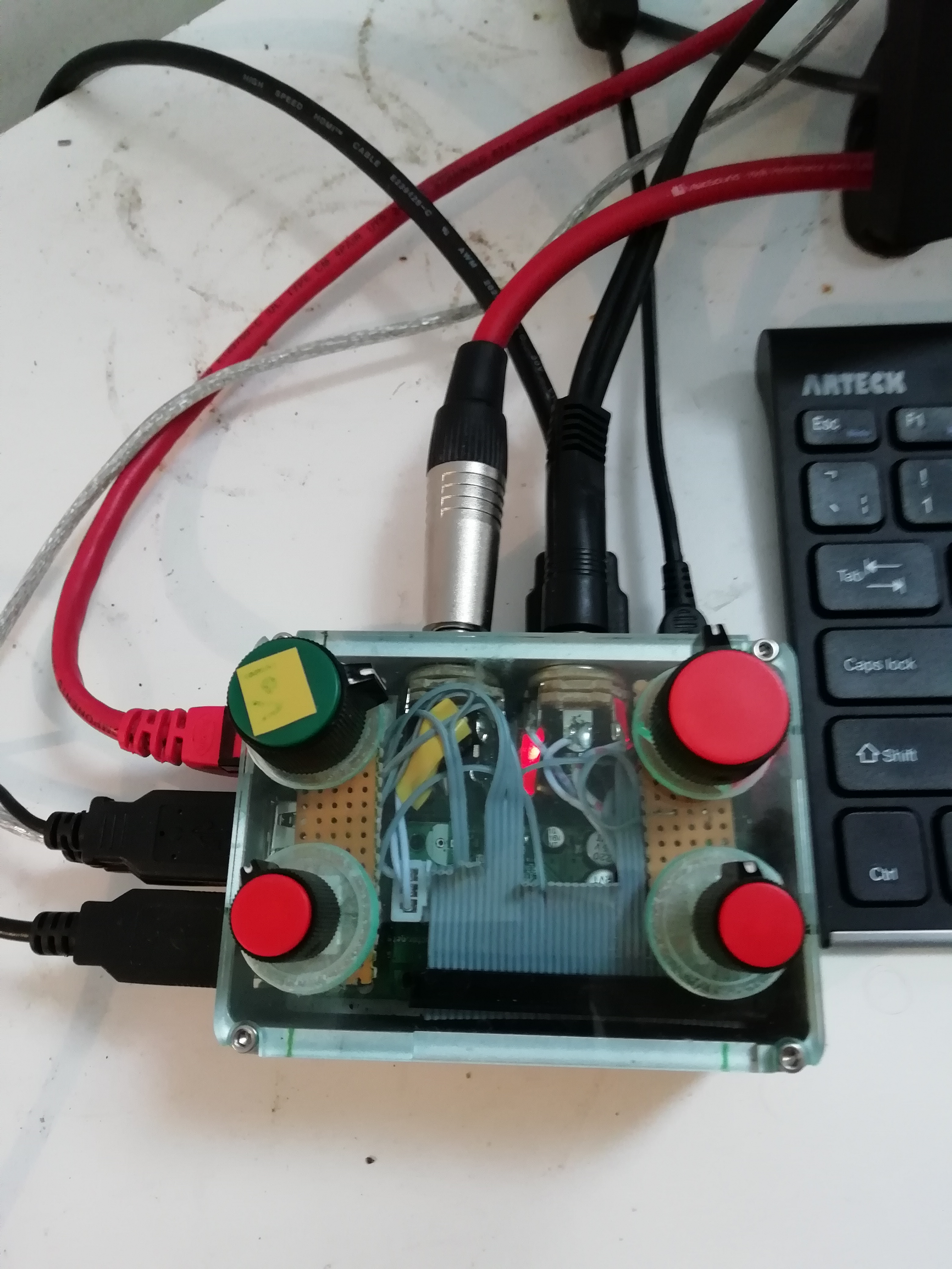
I’ve been building zynthian-alm. It’s an Audio Injector zynth with 4 encoders built on veroboard and hard-wired to the PI 1/0 pins all put together in an nice Aluminium box which out-performs the plastic boxes from the heat point of view . . …
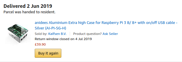
(Mofo if you think you have case problems feel for the case makers of this thing, now withdrawn from Amazon…).
It’s launch was considerably delayed by the failure of the select encoder to scroll in lists ( if you didn’t want to have an encoder fail that is the one you’d choose last so of course…).
Well after considerable debugging, resoldering and part swapping the faultly part was the 40 pin edge connector, apply a little pressure on the top of the connector and all came good, but I suspect it was probably the socket might have become damaged by constantly putting wires in to the connector to check continuity. In effect the metal was only making a connection when the whole housing was slightly warped.
Fix, replace connector (they tend to be cheaper in 10’s).
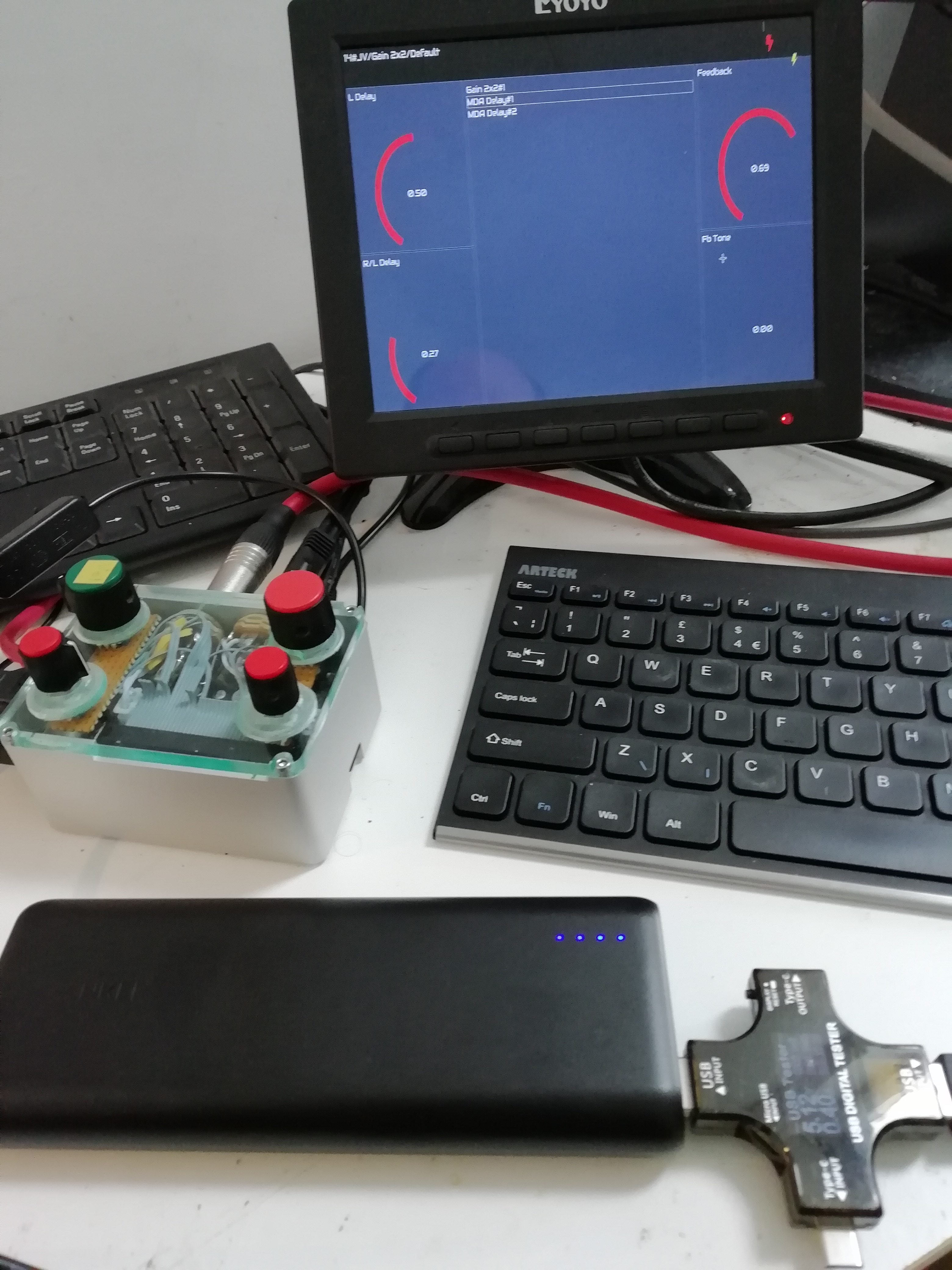
This machine is going down the pub next Wednesday to see if it can last a set as 12 string guitae input with a side order of midi keyboard…
Just added a little echo into the second channel as an effect . . .
All nicely stored as a snapshot for instant recall off the upper right encoder but maybe not on Warren Zevon…
Just running the whole thing off a USB battery pack ( well not the hdmi monitor)
35 years in electronics and never had a single problem with IDC connectors on “classic” flat cables, from the 10 pin serial cable to the 50 pin SCSI, and I usually crimp the connectors using an hammer instead of a vise…
When those stupid ultra-ata cables (80 pin flat cable on 40 pin connector with interleaved grounds) appeared, well, those were a source of swears and curses… even more than the 68 pin ultra wide SCSI cables.
I use a vice but I think they get a fair bit of physical abuse when squeezed into small boxes. Personally I prefer to stack Connectors but I’m quite prepared to admit I have failures especially if you put single strand wires into them to check continuity…
True.
When I have to check continuity I never check through the connector itself, but I have a really thin probe and I use the tip of the flat cable wires peeking from the connector side. When I really have to test using the female connector, I have a breakout board with a matching male connector and test points on all pins.
Talking about 40pin cables.
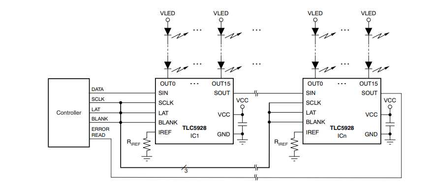
I have a box with 32 LEDs and a 40pin ribbon connected to it.
I would like to address them preferably with an Arduino.
Anybody had experience bundeling it to a couple of digital or an analog pin?
Something like a resistor ladder the other way around?

 But, oh! It is you Wyleu!