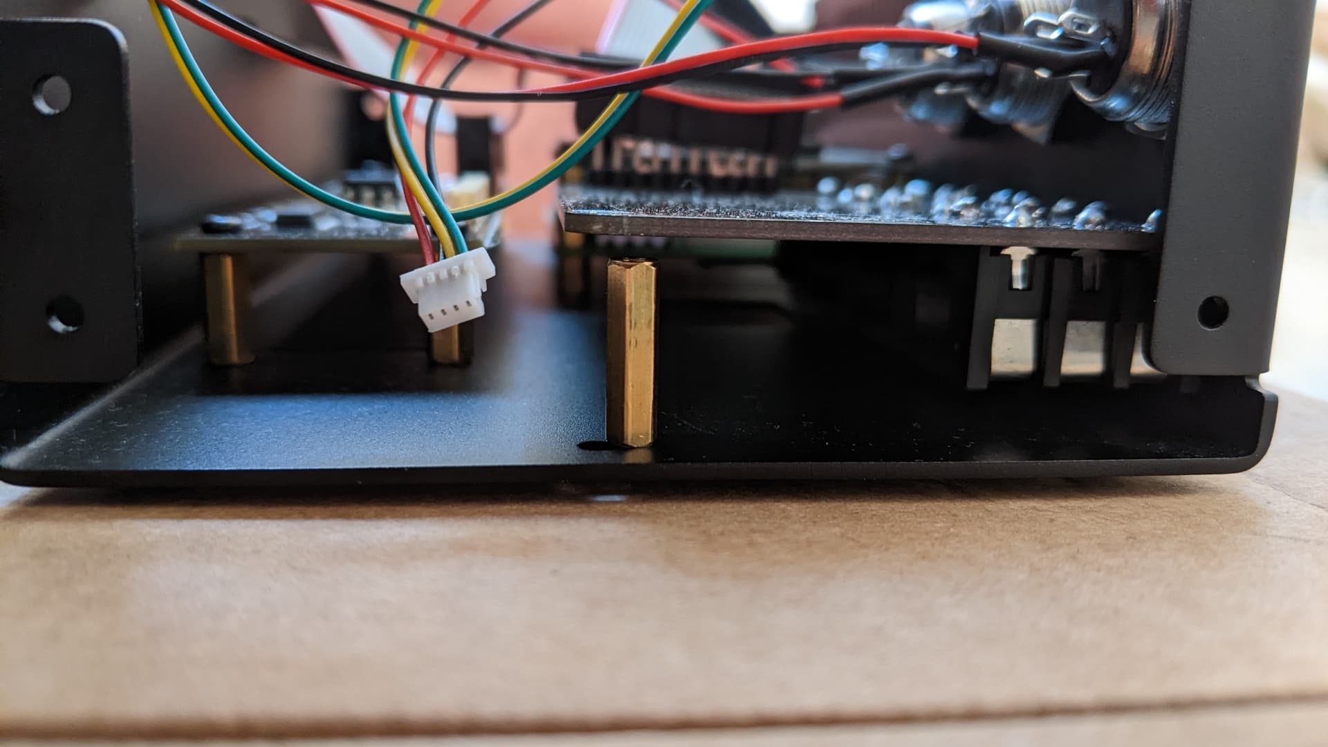
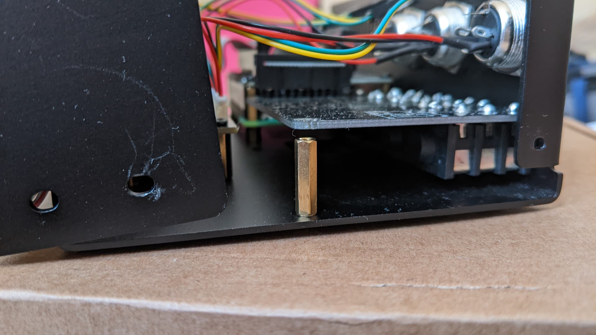
There’s meant to be spacers under the sound input output card but they do not fit which is dangerous as any pressure put onto this for inserting the ribbon cable is bending the card with only the input and output jacks taking the weight.
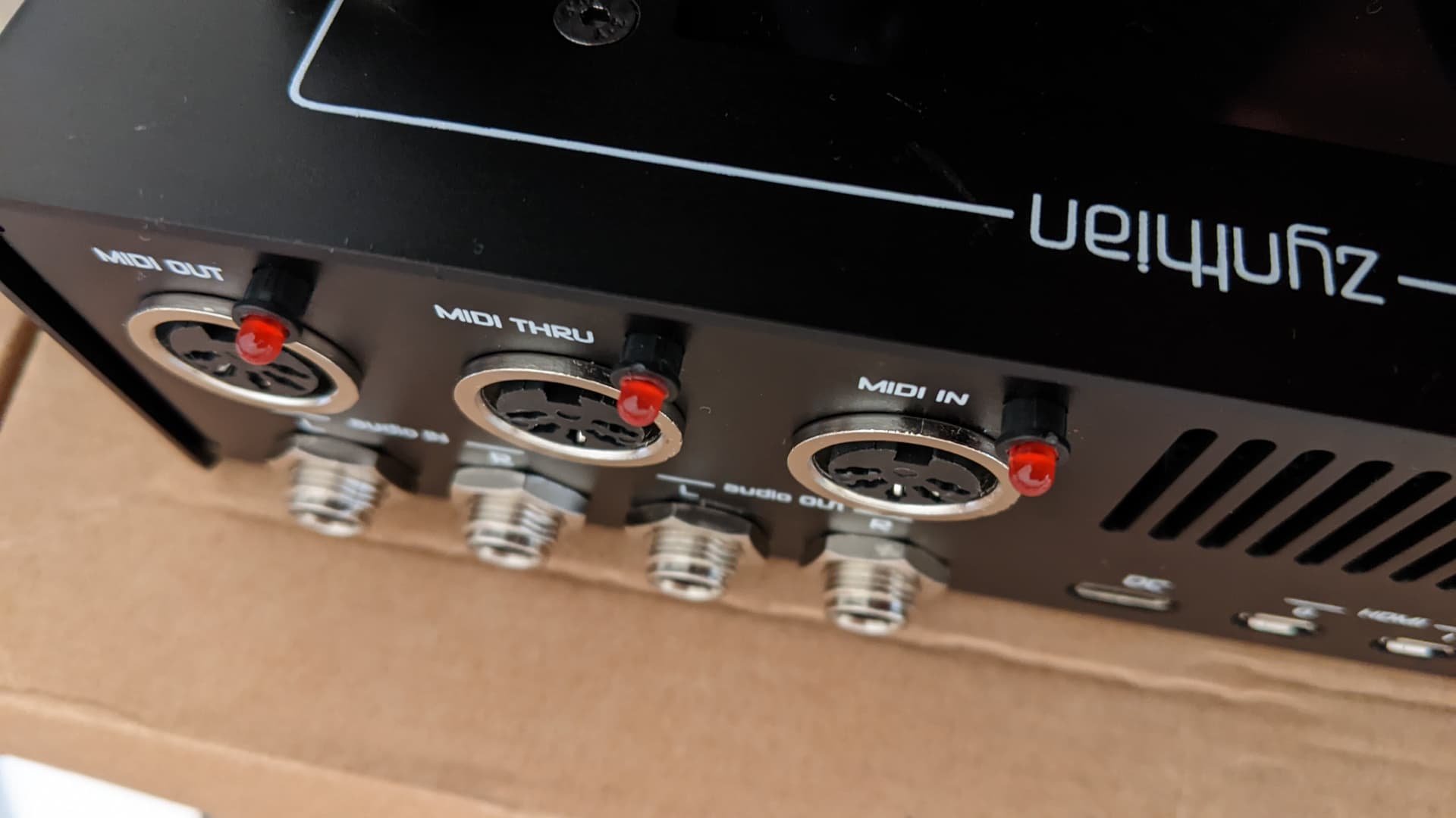
The midi leds do not fit I to the case.
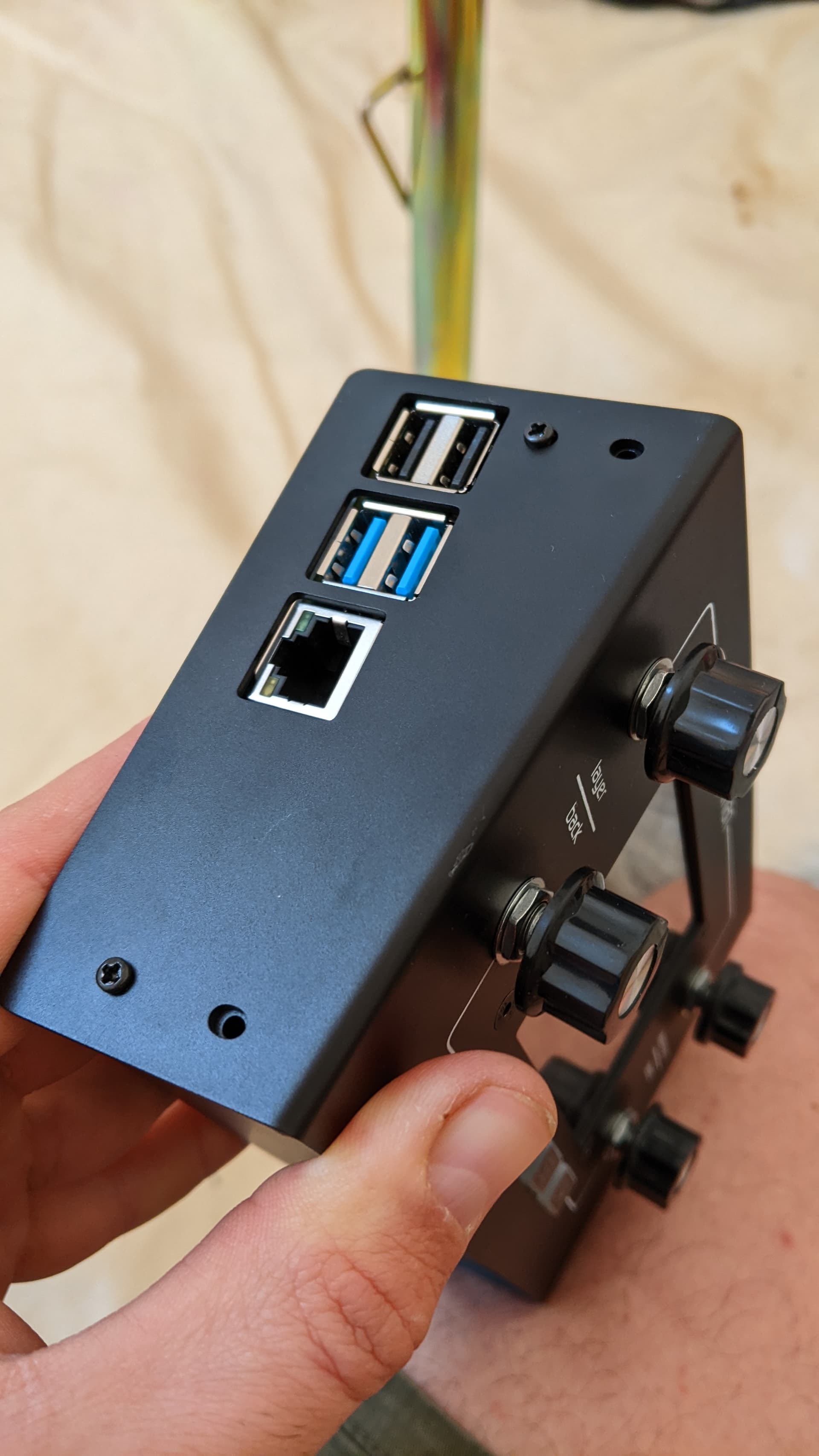
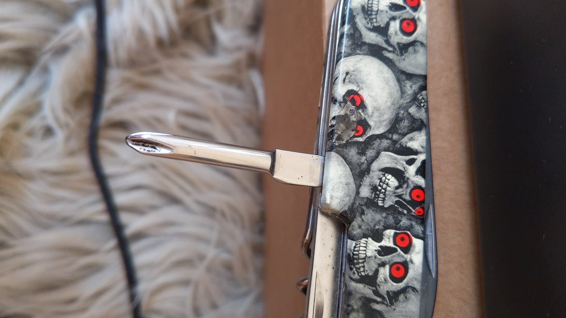
The encoders have a huge gaps under neath Them is that ok?
The 8 sheet threaded screws for the sides of the case do not fit so I used the 4 remaining M2.5 ones probably meant for the spacer for the audio card.
You mentioned a volume knob and having to be extra careful of this when putting the case together but there is no indication where this is and nothing says “volume”.
No where do you explain how to turn it on.
There instructions are very out of date and still refering to the older sound card without the balanced in/out.
Hi! Would you please explain why the spacers do not fit under the ZynAuCon module?
You should have been provided in the kit with 2 x 15mm standoffs that would slide perfectly between the board and the chassis. Did you measure the length of these standoff?
If you say they do not fit, it may well be the case that you have found in the kit some duplicated standoffs and actually missing the correct ones that are supposed to be used to properly fix the ZynAuCon module to the enclosure.
As for your other question about the MIDI leds, I can confirm that they are indeed a very tight fit. You should help yourself pushing the leds in the holes with the plastic outer barrel of a ballpoint pen (BIC style pen).
Lastly, it seems the headphone output and related volume control wheel have been removed from the latest audio boards included with the current kits (v4.6). Apparently, that is a feature that was only introduced with v4.5 but then immediately removed because of some technical issues.
That’s also why you may have noticed that the enclosure included in your kit has no openings to accommodate the volume wheel or headphones out.
Hope this can help!
EDIT: Sorry, I forgot to reply about the encoders. By looking at your pictures, it seems to me that you have properly mounted the knobs on the encoders. The gap you are noticing is exactly the same I can see on my Zynthian. On this particular point, I do agree with you that it would have been nicer if the knobs were more flush to the surface of the enclosure. They are indeed quite high, when compared to the encoders generally installed on other audio equipment.
2 x 15mm height (fem-fem) => For the ZynAuCon module
8 x 12mm height (fem-fem) => For the ZynADAC & Zynaptik
4 x 6mm height (male-female) => For the RBPi
Looking your photo, it seems the spacers are OK (15mm). Please, measure them, and if they are15mm height (14.8 would be also good enough!), please, use the M2.5 bolts to attach the spacers to the ZynAuCon and the case. The boards is not “parallel” to the bottom. You can force it (or relax a little bit the Jack’s nuts), and it will fit nicely.
Regarding the case bolts, they are not metric bolts but self-tapping screws, what does mean that you have to put some force the first time you screw them as they will create the thread . Next time it will be much more soft to do.
You are right @Wuthoqquan. They are hard to push, and i apologize for this, but it was the only way the leds get tight-enough after mounted. If the hole is bigger, the led moves when touched and it feels wrong. As it’s a one-time operation, we preferred the harder-but-safer way.
Instead of applying huge amounts of force to an electrical component it could be a screw or apply a small amount of glue.
How can you say that looks fine Jose??
There is about 3mm gap between the card and the spacer I would have to bend the card to breaking point to have the spacer fit.
I had a similar issue when constructing my V4. I think I left the board floating to avoid undue stress on the PCB.
It looks like the PCB is not parallel to the base which may mean the back panel is not perpendicular or the mounting of the connectors is not true or the connectors are not parallel to the PCB.
Thanks yeah well I screwed it into the case the way it was described I will leave floating as I would not stress it. Seems a design fault the parts do not fit together.
Yep! Just plug the power in and the magic begins. These devices do not have power switches. This can be slightly irksome because you need to interrupt the power to turn it back on after powering down (from UI). Don’t be tempted to add a switch to the 5V line. This will increase impedance which adversely effects performance.
Zynthian peaks to 3A current drain but sits below this most of the time. This means that the supply must be capable of providing 3A for short periods. Many devices can do this. I have run mine from a 5V UPS (which is effectively a power bank) and it worked fine despite being supplied by a lower capacity PSU. The PSU charged the UPS at a max current of 2.5A and the UPS provided 3A peak but average draw was below 2.5A so the UPS remained charged.
The important thing is that the power supply can provide 5V @ 3A at the Zynthian when required which means it needs to have this max peak capacity and have low impedance cables and connectors to reduce voltage drop across the interconnects.
Note to @jofemodo: It may be advantageous to add some supply conditioner within the device, e.g. something that provides peak current on demand - like a big capacitor!
Yes I will try it, I did see a red and green light on the PI board light up with the power bank in so that is a good sign, but when I turn it on the screen does nothing, I have no SD Card in there yet so this does not have a BIOS or equivalent?
Now I am trying to flash the zynthian img to the micro sd with raspberry pi imager and it is not seeing the img file.
In fact even if I put it to “all files” it does not see anything?
Still I cannot get the case screws in I think it’s a bad design choice and requires way too much pressure to force them in and they will screw in at a wonky angle, how am I supposed to unscrew them afterwards?
I will get more m2.5 screws as I have only two in each side now but it’s working !
Ok I loaded sfz drum machine linn9000 2
I have my midi keyboard plugged in.
No sound?
I see there is midi going in and the green levels lighting up.
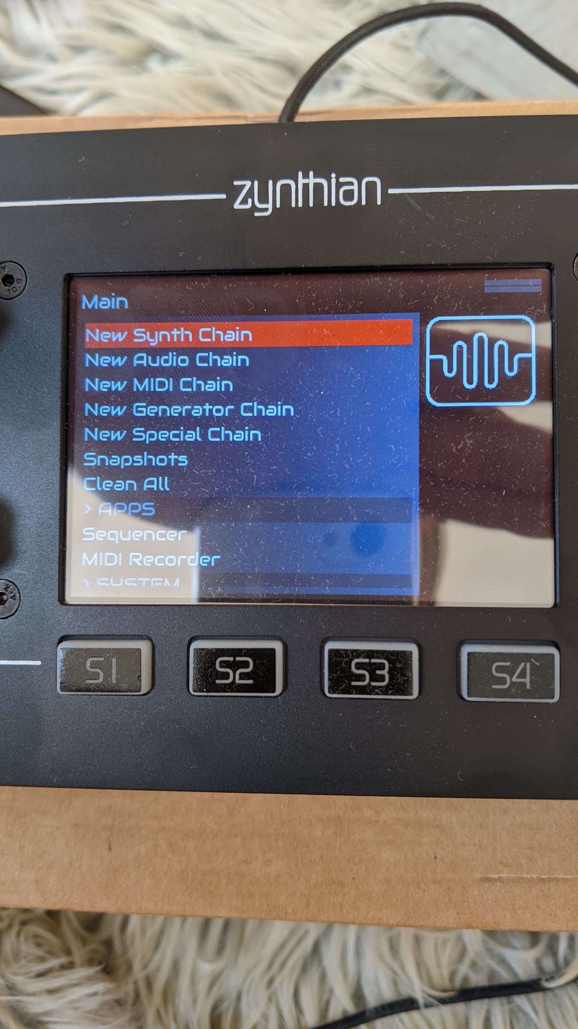
Also how do I get back to the home page? I looked everywhere and pressed everything and rebooted and still I cannot get back to the new layer page.
I tried long pressing everything and still cannot get back to home screen or any sound I ran the audio test and no sound:(
The touch screen is useless it’s impossible to make it respond to anything it does not detect a press unless I try 10-20 times and so small I cannot select different manu items. Is it resistive ? Never used such an awful touch screen before.
I think you may be being a little too hasty with the negative feedback pal. I assume you have the V4 kit purchased from the Zynthian shop. The screen is a fairly low cost / value screen. This was a design decision to keep the cost of the unit low. Self tapping screws are a well established fixing method that again keeps cost down. They work very well and I find the process quite satisfying. You get the right screwdriver and carefully screw into the metal, keeping everything perpendicular. Slow and steady progress. The screw cuts its own thread. I tend to use a tapping technique, i.e. unscrewing every couple of turns to allow swarf to free. (This isn’t really needed here but I am used to doing that.) I wouldn’t recommend using a penknife to do the screws. It is much easier with a proper screwdriver of the right type. (I think these are Philips head, not Pozidrive or Superdrive but a Philips 0 or Pozidrive 0 both fit well.)
You talk about “layers” but if you are using the latest image then we stopped calling things layers with that release. Make sure you have the current image and it is updated.
Check the user guides which was updated to describe the current stable version. If there is something not clear, please help us by describing the issue.