Hey all–
I’ve already done a dev Zynthian by burning Gorgona to a micro-SD, and modifying the crap out of some settings to do HDMI instead of TFT, using the onboard sound card, and using a USB MIDI controller. Later, I even went so far as to buy a Hifiberry cause the onboard soundcard obviously just wasn’t cutting it  . Anyway… now I have my own kit! @jofemodo sent me one and it just arrived this past Friday.
@jofemodo was nice enough to do all the soldering for me, so I’m at the wiring/connecting phase. Obviously I’ve been helped tremendously by the instructions on the blog and in the wiki, but I’ve hit a small issue I’d like to share with the community.
First off, PICTURES!
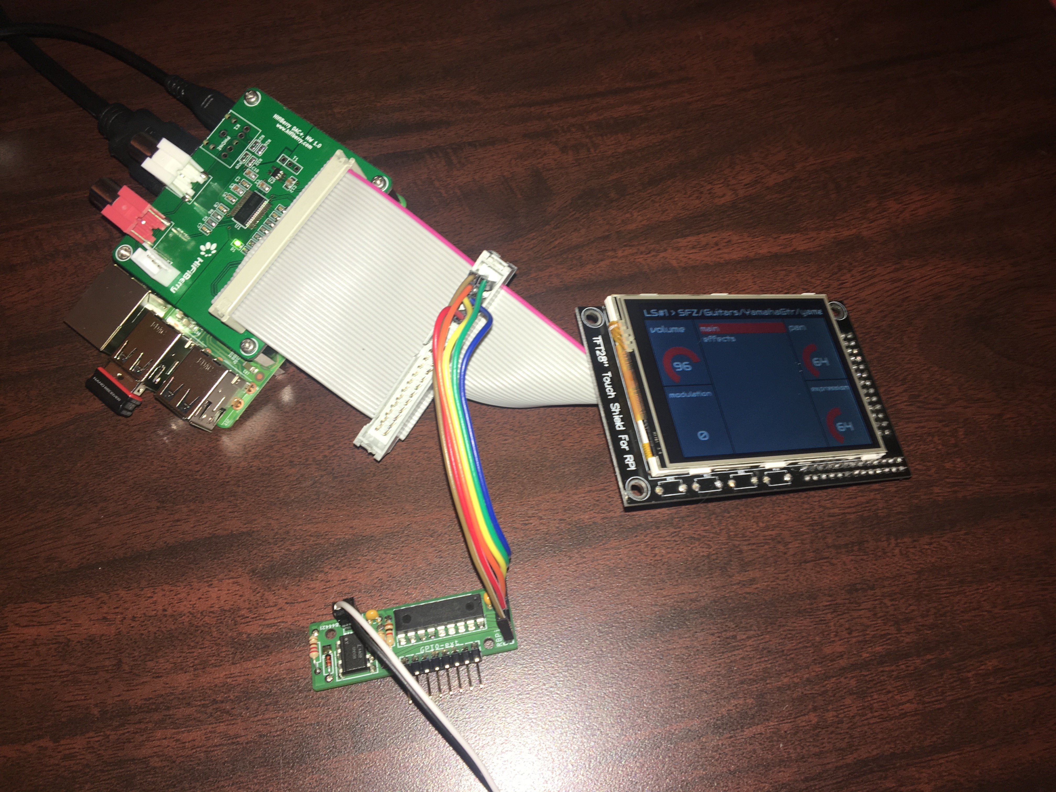
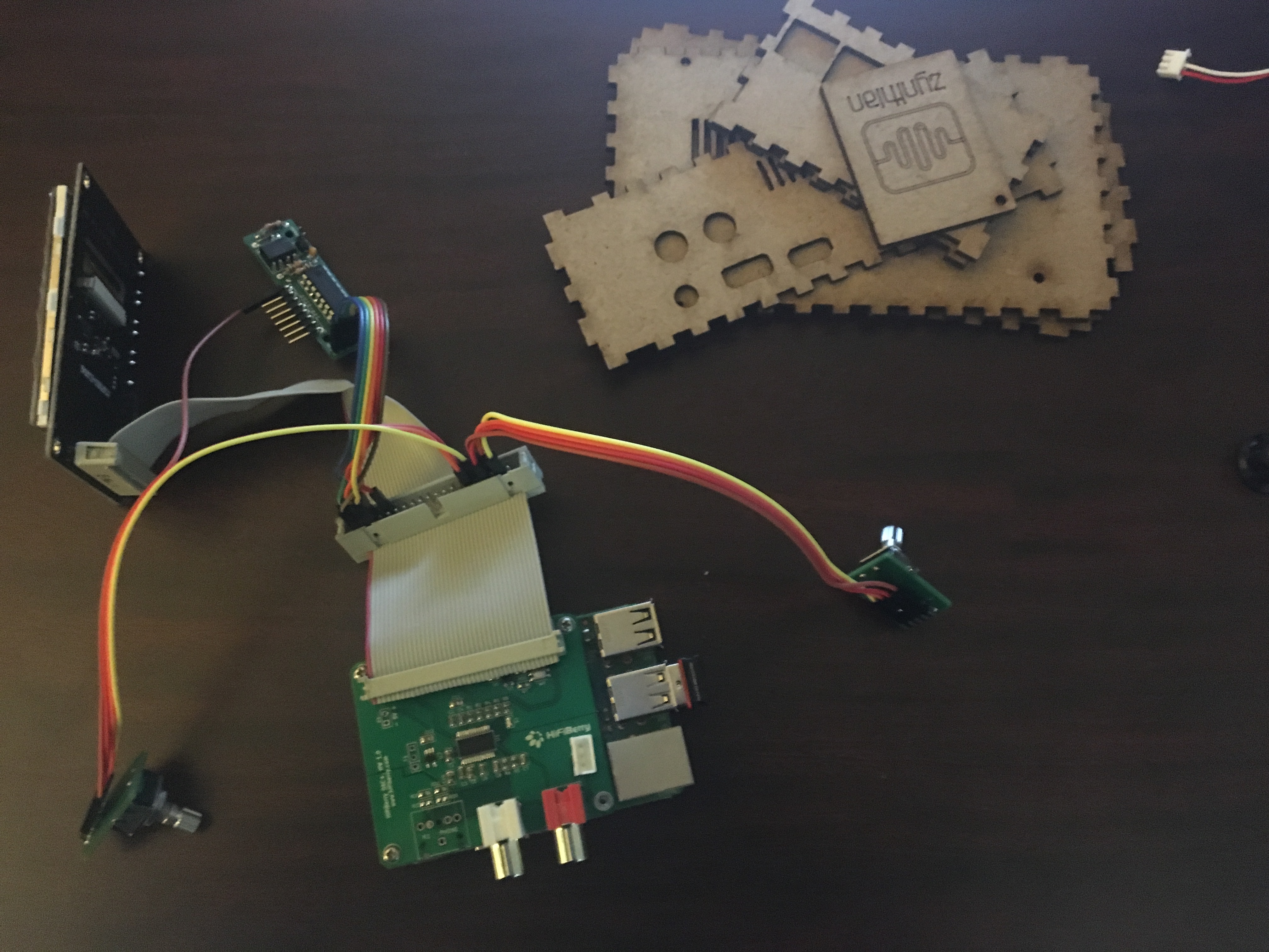
Everything laid out and ready:

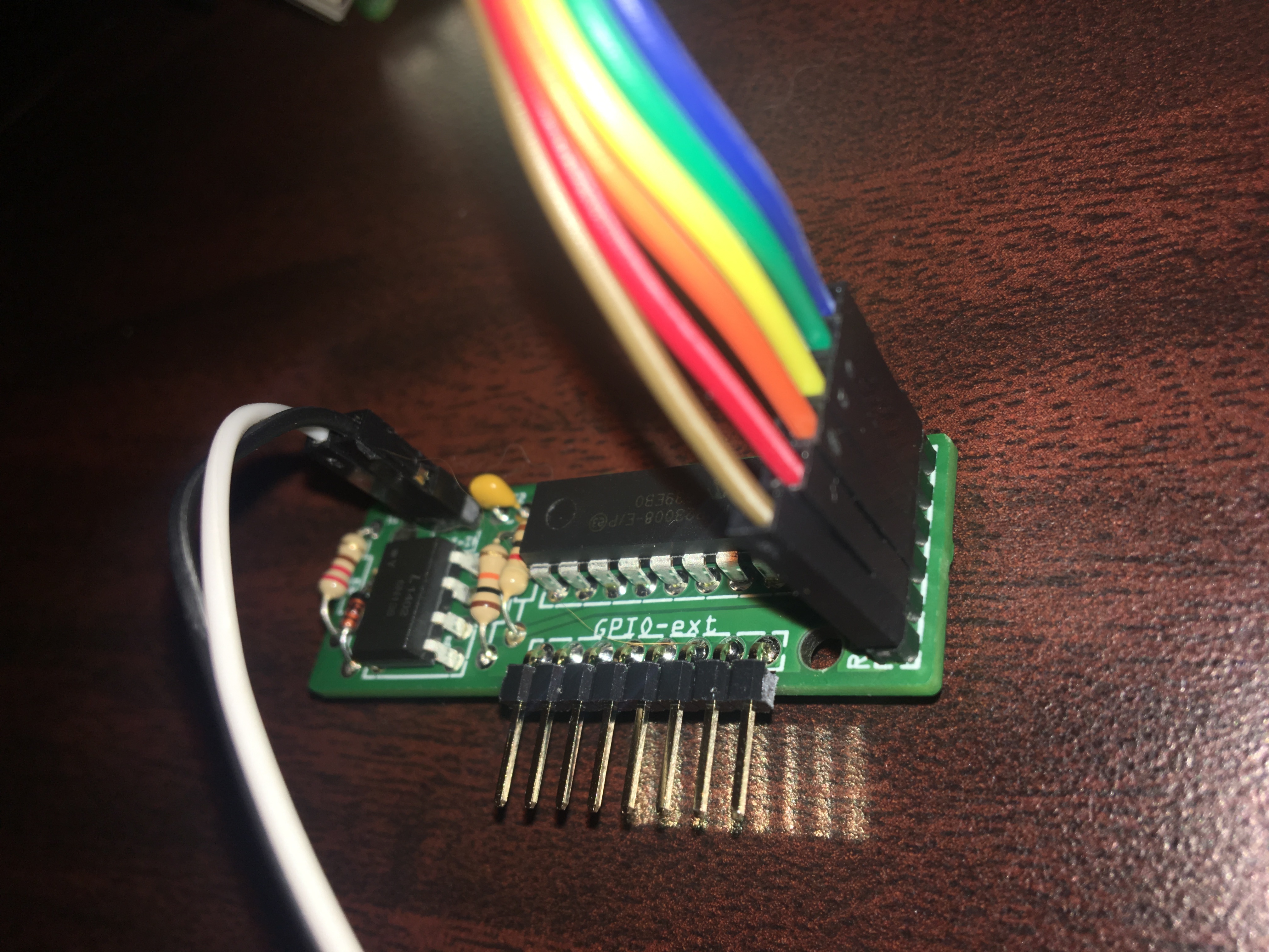
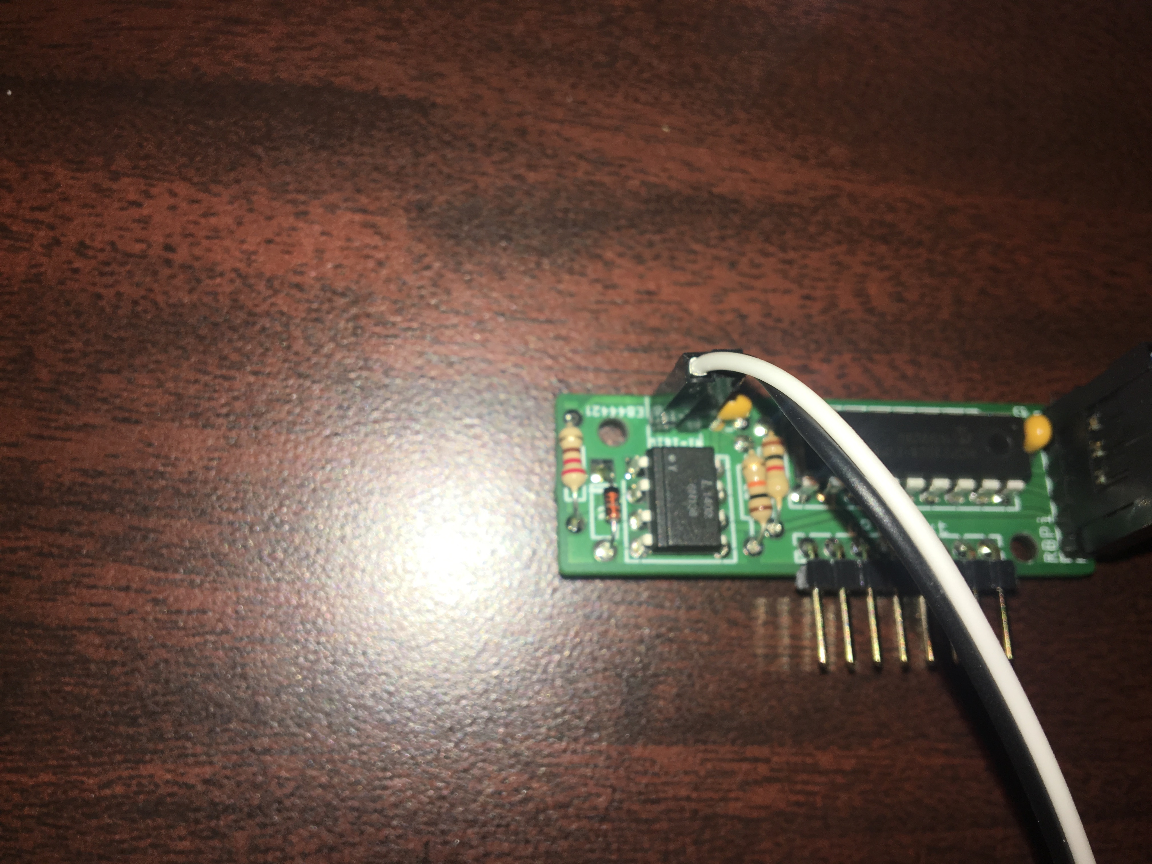
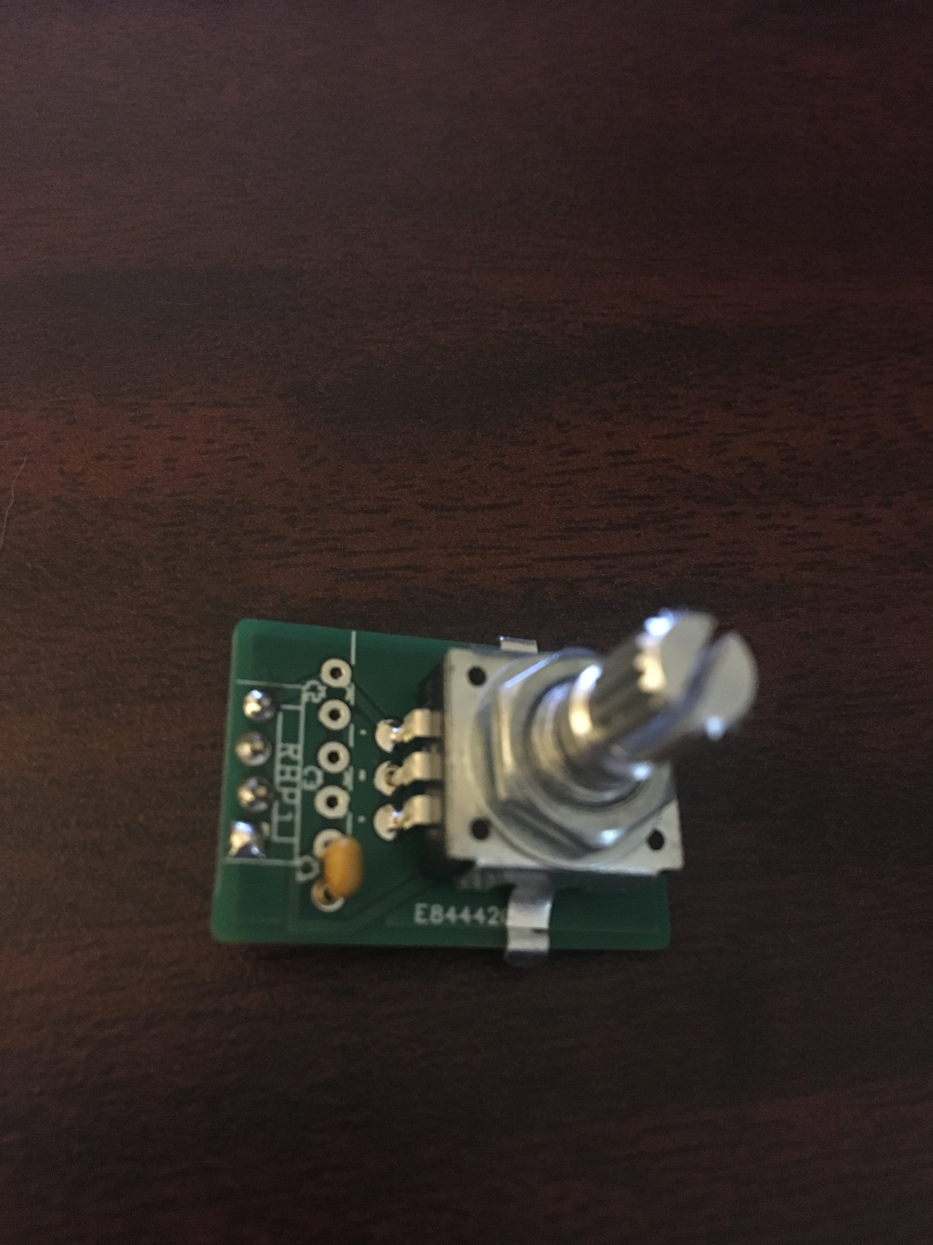
A rotator–part of the question.
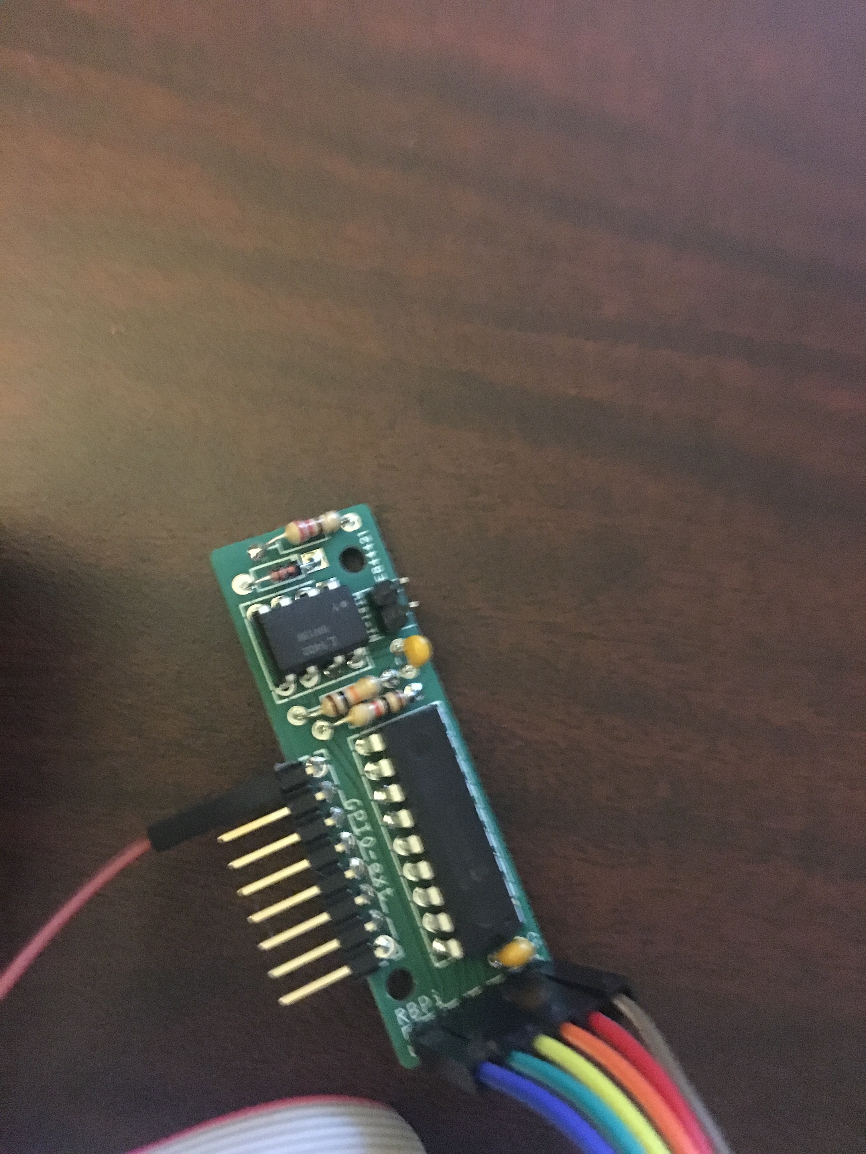
The 2-in-1 PCB:
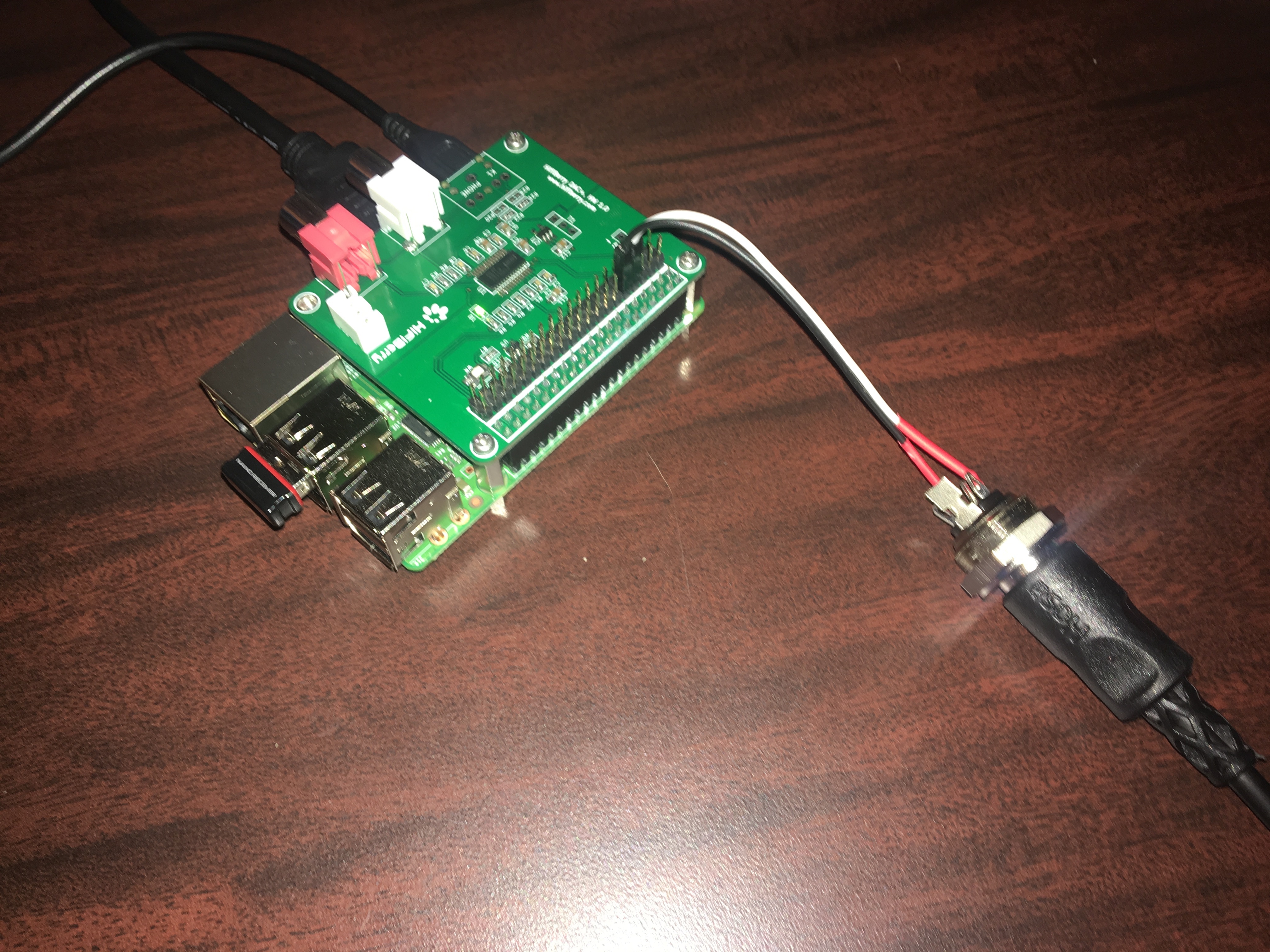
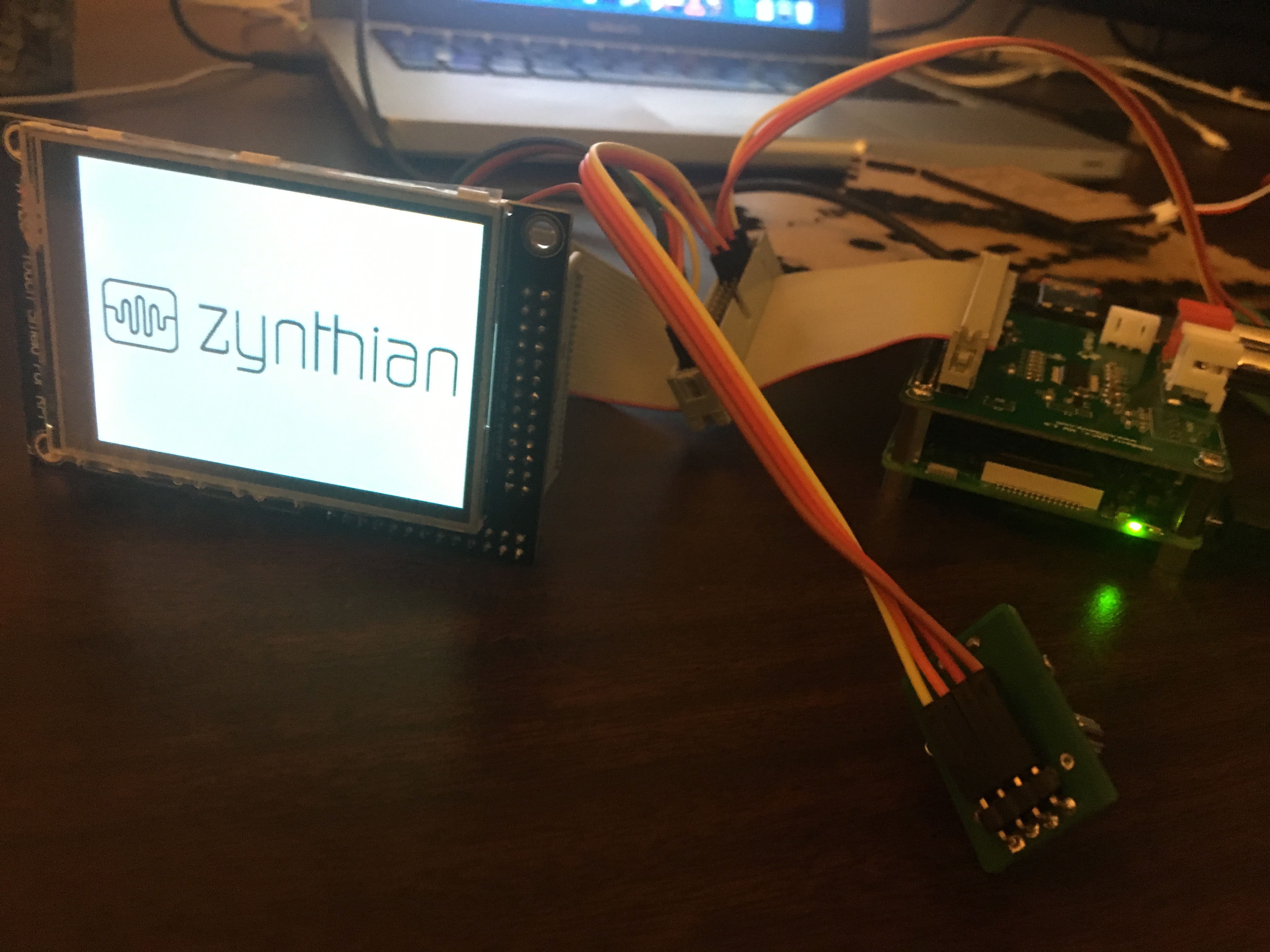
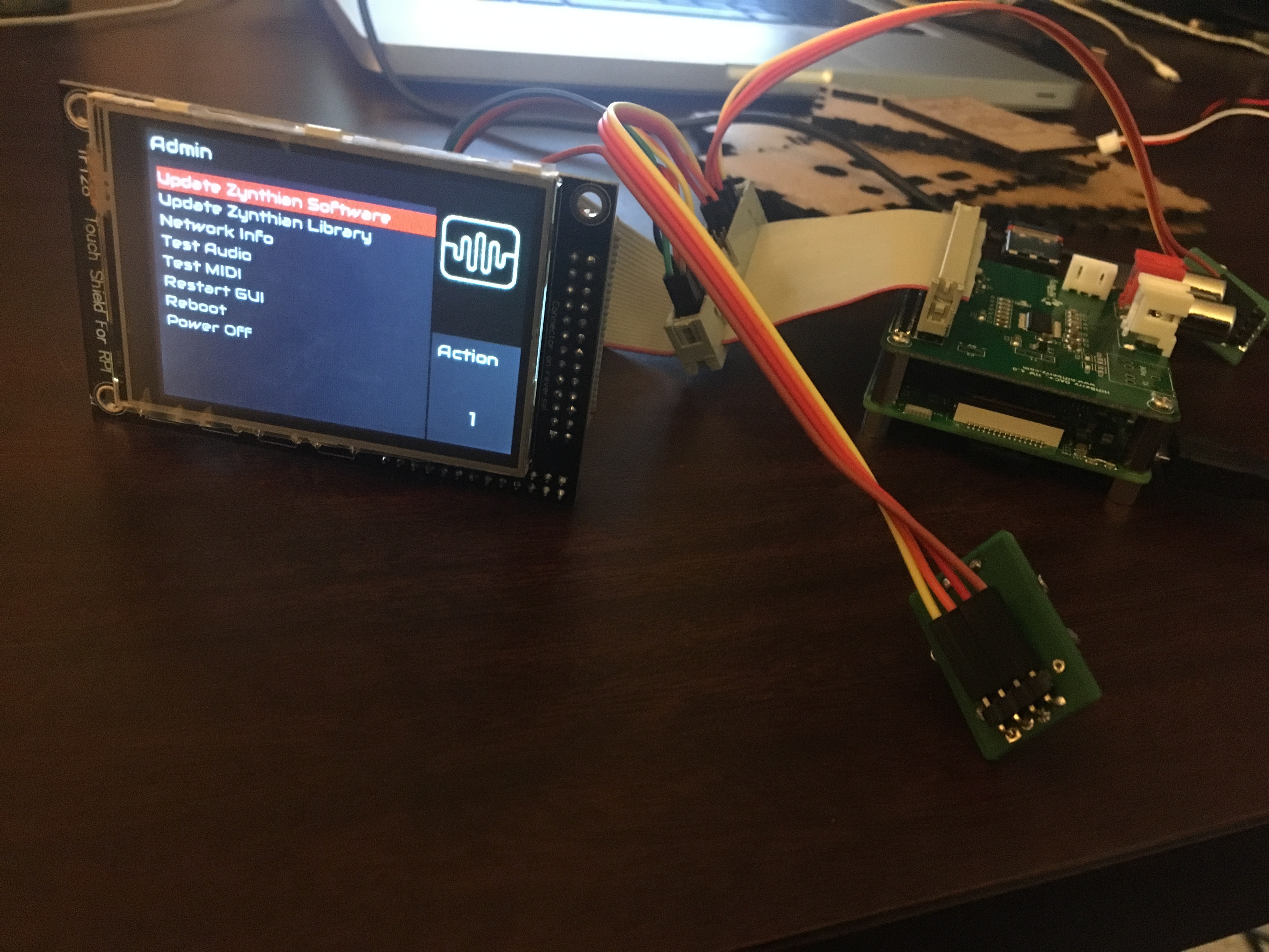
What I’ve assembled so far:
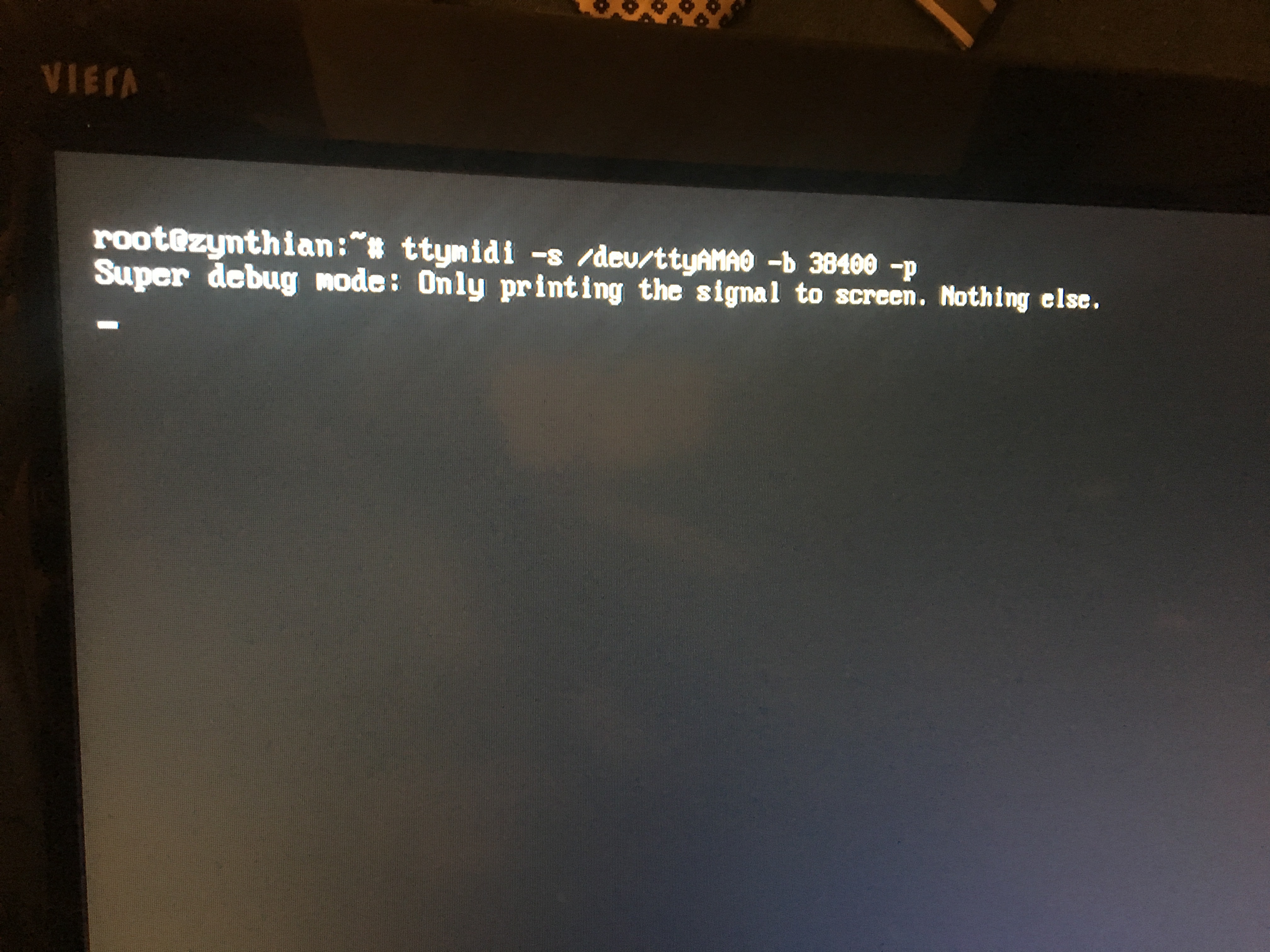
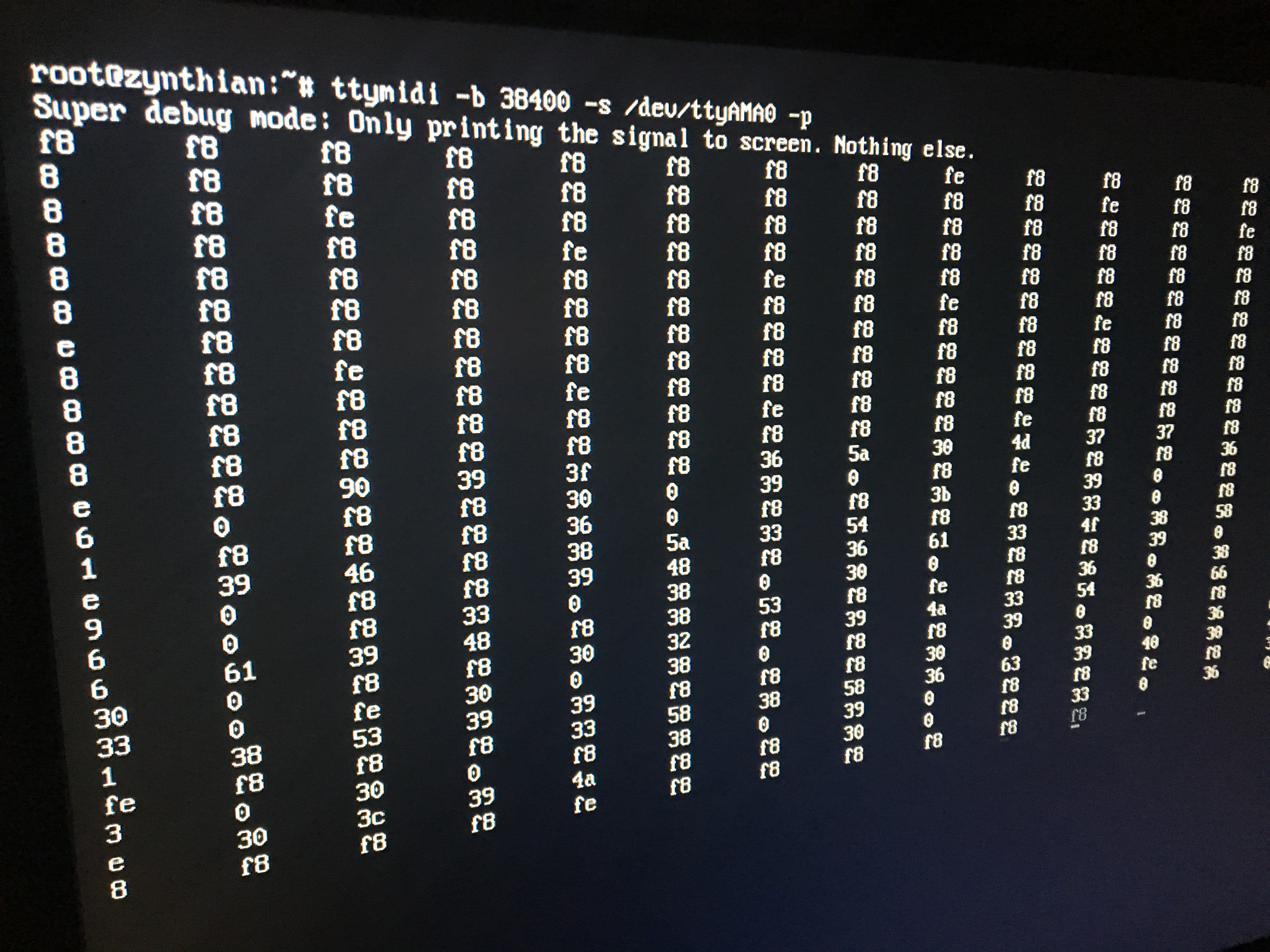
The splash screen!
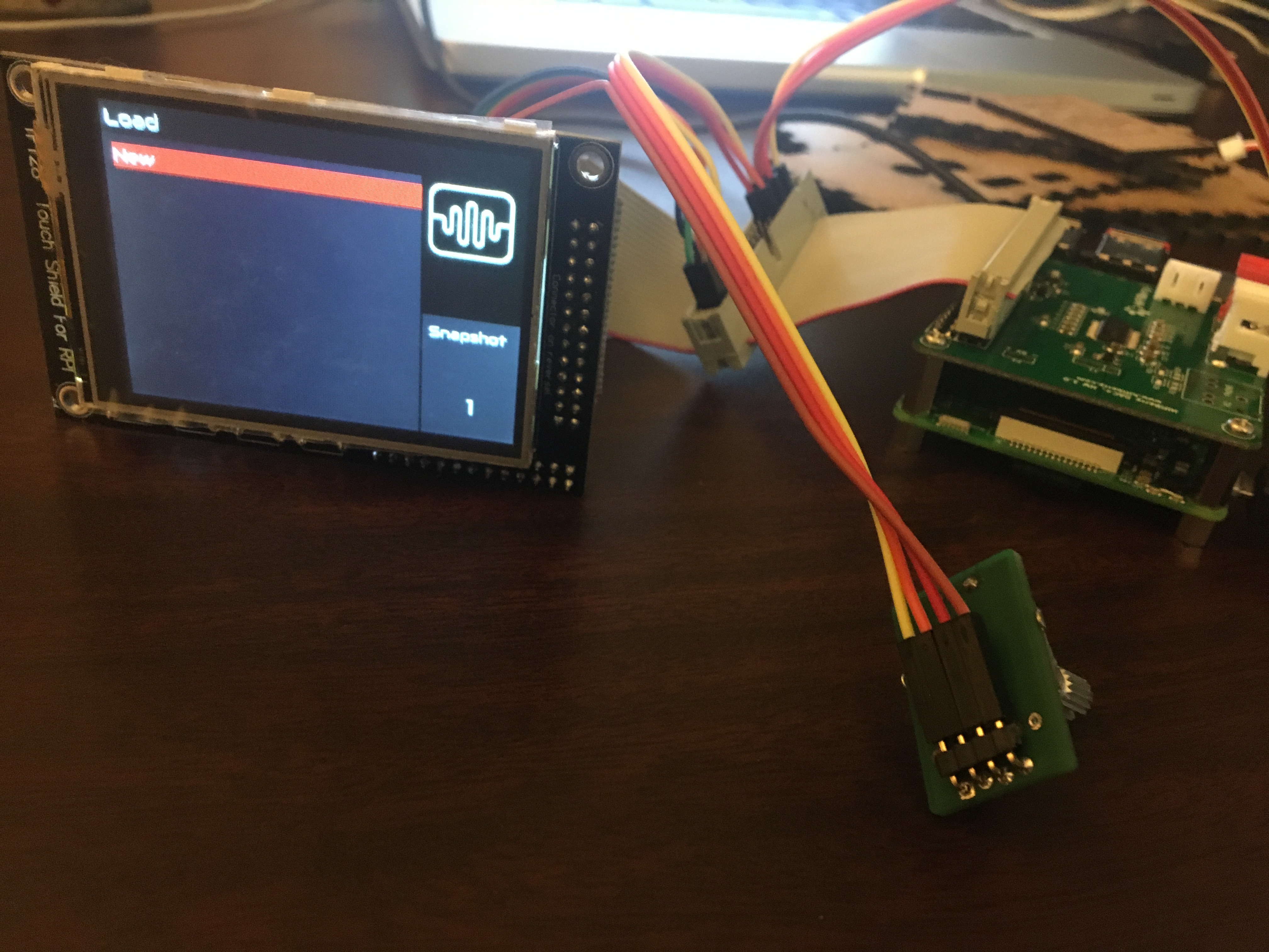
Select a preset:
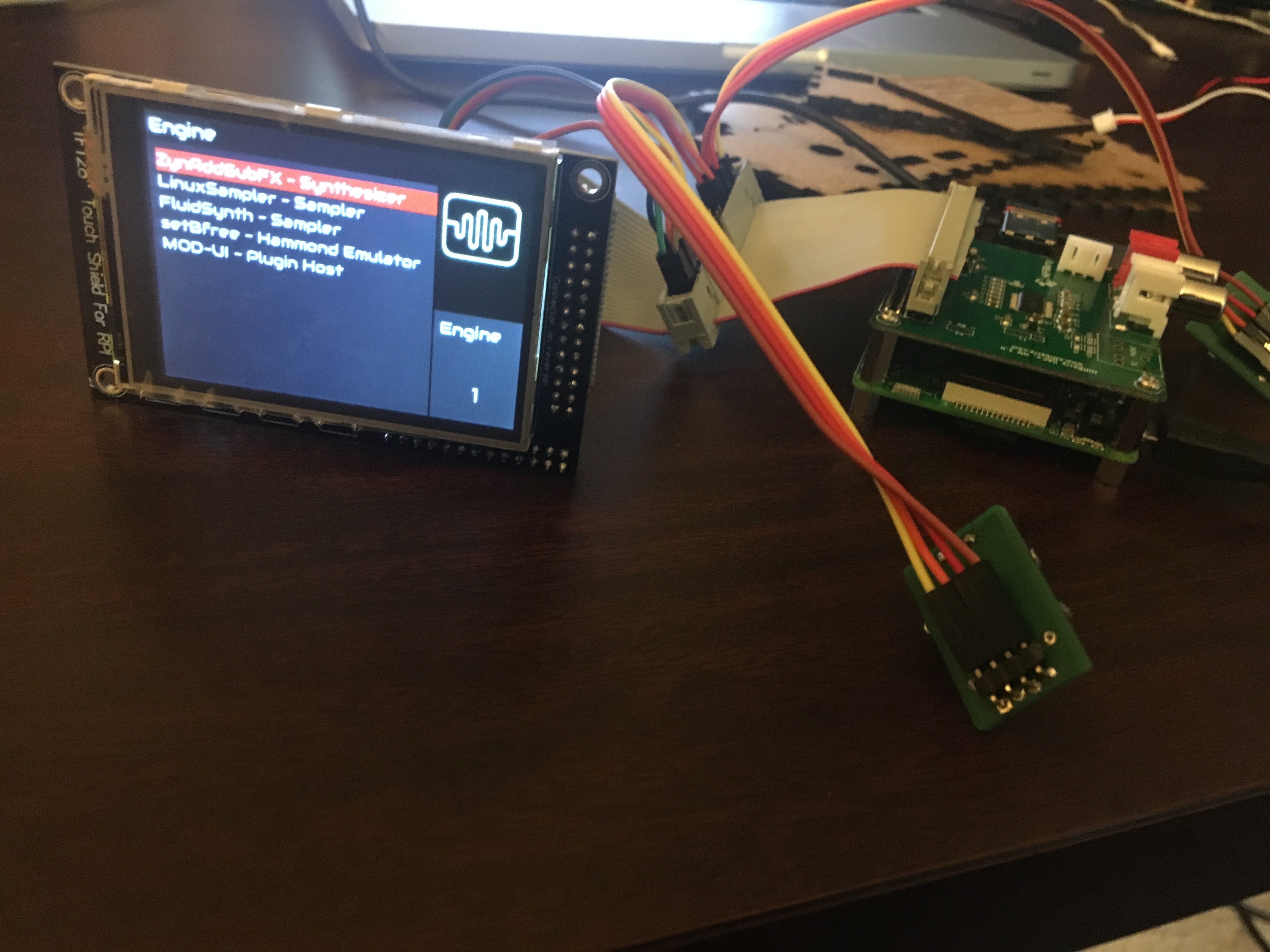
Choose your engine:
Admin Menu:
So I’m super excited, for obvious reasons, but I guess my question comes down to this:
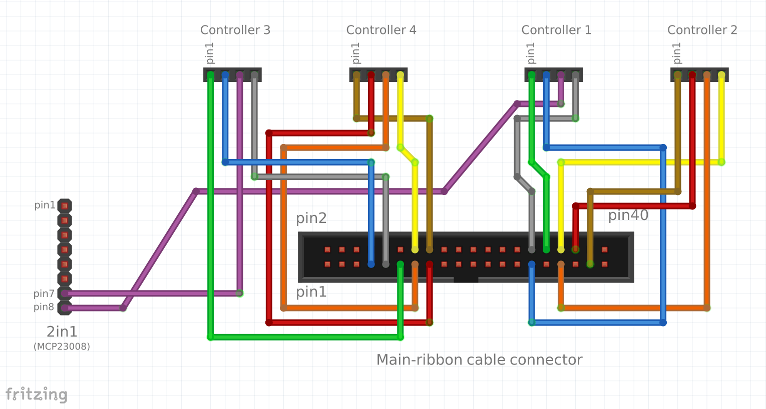
In this diagram, from the Wiki, pin 1 or in general the ordering / numbering of pins is very very important… the color of the wire lines here doesn’t matter except as to help you connect the right pins to the right pins… right?
So I guess my situation is, if you look at the rotary encoder picture up above, maybe someone can use that picture or give me another way to deteremine which pin is pin 1?
On the ribbon, it’s a bit easier, I think, because you hold the ribbon such that the little slot in the middle faces down, and then pin 1 is the bottom left pin, pin 2 is the top left pin, and they go like that across the ribbon. No sweat. I’m having trouble finding a way of reliably identifying pins on the other components–particularly the 2-in-1 and the rotary. Forgive the n00b question–I’m a software person, not a hardware person 
So, that’s one major question, and I guess the other is this: do all 4 rotary controllers have to be connected, and also connected to the 2-in-1 to get a working UI navigation control? I ask because with just two connected (controllers 1 and 2), all I can do is go back between the admin screen and the engine selection screen endlessly. With what I have, pushing in a rotary doesn’t select anything, and actually the other controller doesn’t really do anything.
Of course, I can follow the rest of the instructions, go ahead and connect the other rotaries, etc, but I wanted to make sure I’m doing it right before I move on–particularly given that I’m having a hard time identifying pins.
Thanks in advance for any help on this issue! I now know why people use so many exclamation marks (!) when they post that they received their kit or started their build!