Excited at first, but disappointed now, as I can’t manage to get it start properly.
I have built the hardware according to Zynthian’s official doc and prepared the last official image for a SD card.
When my Zynthian kit is powered up, my raspberry Pi 4B (8G) doesn’t work properly, as only the red led on the Pi’s board is on, while the green led, which is just next to the red one, just remain off, http://res.makeronsite.com/billy/my_zynthian_kit_1.jpeg
Then I unassembled the Zynthian kit, took my Pi out, connected it to a screen via HDIM, powered it up separately with the same official image. The Pi seems OK at the start, as the red light is on and green flashes, and the screen showed a classic raspberry’s boot start at the beginning, but the terminal stops at a blank, black screen with only one single underline about 30 sec, then flashes in quite some messages, which the last line is a wait for a Zynthinan user login about 1 sec, back to the blank, black screen with only one underline again and over again, http://res.makeronsite.com/billy/boot_problem.png
What problems I may have here? A hardware or software problem?
Would any one guide me how to tackle it?
You need to see the green light show some activity, so It sounds like a hardware issue,but could of course be both software and hardware. Don’t dispair, we’ve rescued many a zynth…!
Check the orientation of ribbon cables and make sure that they are all connected properly. I’ve frequently only plugged one row of pins in and offset connectors by one row. Also give the boards a visual inspection. Look for dry joints (not shiny or not soldered) . Do you have a multimeter? That can help check shorts on power rails.
You say you can start the pi. A default setup won’t start up if it can’t find audio components so you will need to use the webconf on a browser (webconf should start), to reconfigure the machine to test the sd. Remove all the zynth components and see if you can start it as a headless machine (webconf kit custom, dummies for wiring and audio and select hdmi for display) that should tell you that your ssd is
OK.
I tested my Pi with a normal Pi raspbian official image, according to Baggypants’s advice. The Pi works OK, therefore, my Pi 4B seems to be fine in term of hardware.
I think there is a problem in the Zynaptik module. Here are what I did:
When I turned the Zynthian kit on without wiring the 40 pins ribbon cable to the Zynaptik module (the long board that has three MIDI ports), the Zynthian system got to work and the Zynthian touch screen showed an error image with the Zynthian logo and “IP:”, as the following png is shown. http://res.makeronsite.com/billy/my_kit.png
On the other hand, when the Zynaptik module is wired up by the 40pins ribbon cable, the Pi doesn’t start up properly. The LED red light on the Pi is on, but the green LED remains off. Nothing is showing on the Zynthian touch screen. I guess, there is a sort of short circuit in my Zynaptik module? I have a multimeter. How I shall check pins on the Zynaptik module?
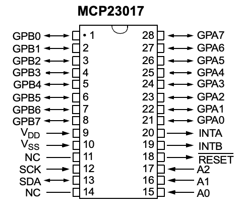
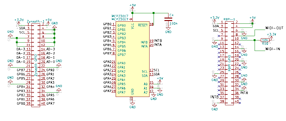
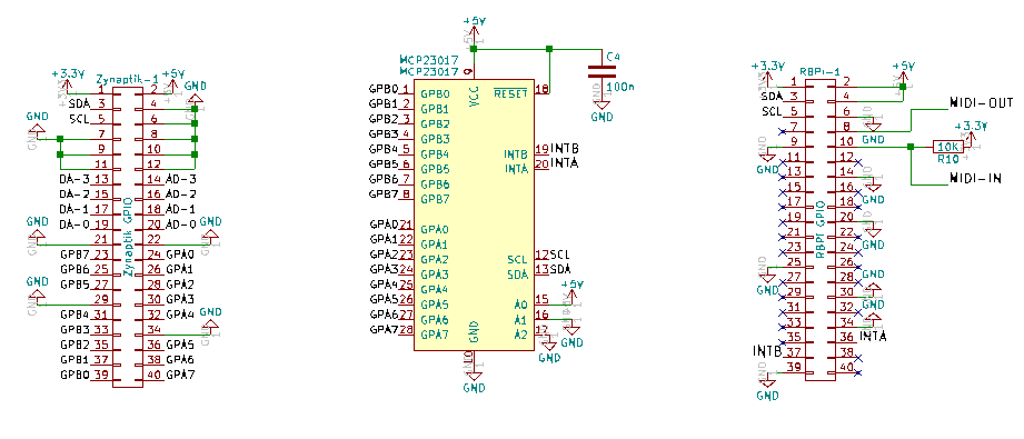
There is an order, to apply to any bits of electronics that show issues like this. Your starting point is schematic for the zynaptik of which the following are the highlights.
https://discourse.zynthian.org/uploads/default/original/2X/8/81ba3d877e039d8f43ca380528b021ec3bd034ef.png
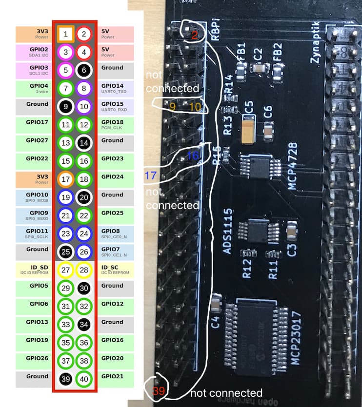
Your first concern is the power rails, +5v and +3.3v.with the board disconnected identify the appropriate pins on the RBPg1 connector (pins 2 and 4) and use the multimeter to check if there is a short circuit to ground (0v) connection.
Use the continuity setting (the buzzer) basically putting the multimeter on pin2 and pin 39 shouldn’t buzz but if it does reverse the multimeter connections and see if it still does then you have identified the problem.
If it does the next stage is a careful visual inspection as with the thread No sounds from the 1/4" outputs (soundcard) - #20 by fschenckel, take a picture of the main chip on the board and post it here. There are some pins that should be connected to earth (0v) but not all and what you describe sounds similar to this thread.
Please post some pictures of the PCB (both sides) which may allow us to help diagnose issues. Also pictures of the cables when connected to all the boards. As previously mentioned by our esteemed @wyleu it is all too easy to connect these up incorrectly. Even I have done it (more than once) !!!
I think I have found the problem in MCP23017 chip.
If you look carefully, the second and the third pins from the left side are short, and I have checked it by my multimeter.
Although I have a soldering tool, I’m not sure how to fix it…
It seems quite a delicate work
I tried a few times to separate these two pins, but I failed…
I’m afraid I may damage the PCB if I tried too hard…
I’m a bit confused now… the MCP23017 chip on my Zynaptik module does’t match the schematic you sent to me above. (or I may misunderstand something here?)
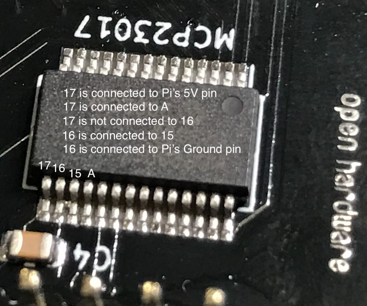
I used my multimeter to check the four pins from the bottom left as the below picture, I got this:
17 is connected to Pi’s 5v pin;
17 is connected to A (as indicated in the picture);
17 is not connected to 16;
16 is connected to 15;
16 is connected to Pi’s ground pin
Are there anything wrong, or things are just fine here for these four pins?
Without removing the chip ( and I REALLY don’t suggest trying that!! ) I would suspect that things are probably ok with the chip, but do of course photograph the other side as well. Electrons care not a jot about physical orientation and will just flow down any path that they can, which is why this sort of fault finding can be a bit of a pain. What does the multimeter across the the edge connectors pin’s 2 & 39 report? If that’s a dead short then the problem is on the board, if not then the problem is elsewhere. You could also make the same check with the multimeter on pins 9 and 10 which are the 0V & +5v supply to the chip, but of course if there is a short all these points will be connected.
IT’s worth going round the chip and see if there are shorts between any of the pins. IN some cases (16 & 17) there will be shorts but the schematic should indicate this.
Once you know the fault is or is not on a particular sub component ( a board for instance) then a magnifying glass and following the track carefully often reveals a problem.
There are some impressive mechanisms for fault finding issues but these are tools for the professional. I’ve seen thermal cameras used to do this sort of thing and if one has two hundred boards o check a day those are godsends, but we are not in that world.
Jofe operates a very generous approach to this sort of thing, but it’s wise to actually tie the fault down to the component to avoid perfectly good devices cluttering up the postal system with all the joyous expectation and disappointment that can involve.
As I said electrons don’t care so be as suspicious of edge connectors and ribbon cables as of components and boards. Make ABSOLUTELY sure you have the connectors the correct way round and ensure that you haven’t managed to bend a pin or offset the connector by one pin or only connected on one row of the edge connector. One frequently makes assumptions about which pin is 1 and which row is which and these can be particularly insidious faults. Just because it looks like that is the correct orientation, doesn’t necessarily mean it is. Check with photos of working units…
I have done all of these at some time and lost many an afternoon, to an increasing belief that some vicious electronic Demi-God has got it in for me personally. REmember even @riban has done this ("Even I have done it (more than once) !!!) " and he is worshiped like a god by many of the ill dressed natives of the Essex hinterland…
You do at least have the reassurance that the design is sound and it works. When you design stuff yourself you are also fighting the fact that the whole idea might be faulty, and that is a real learning experience !!
Modern electronic components are generally pretty rugged. I once soldered a CA3130 in a sample and hold circuit the wrong way round, I misread the schematic, and as a result it got HOT!! hot enough to burn it’s lettering into my finger in reverse when I touched it. IT still worked once I corrected the mistake which was rather good because the chip had cost me my entire pocket money that week to buy. ( I was 15 ) …
Keep going. You will learn far more from this than if it all works first time.
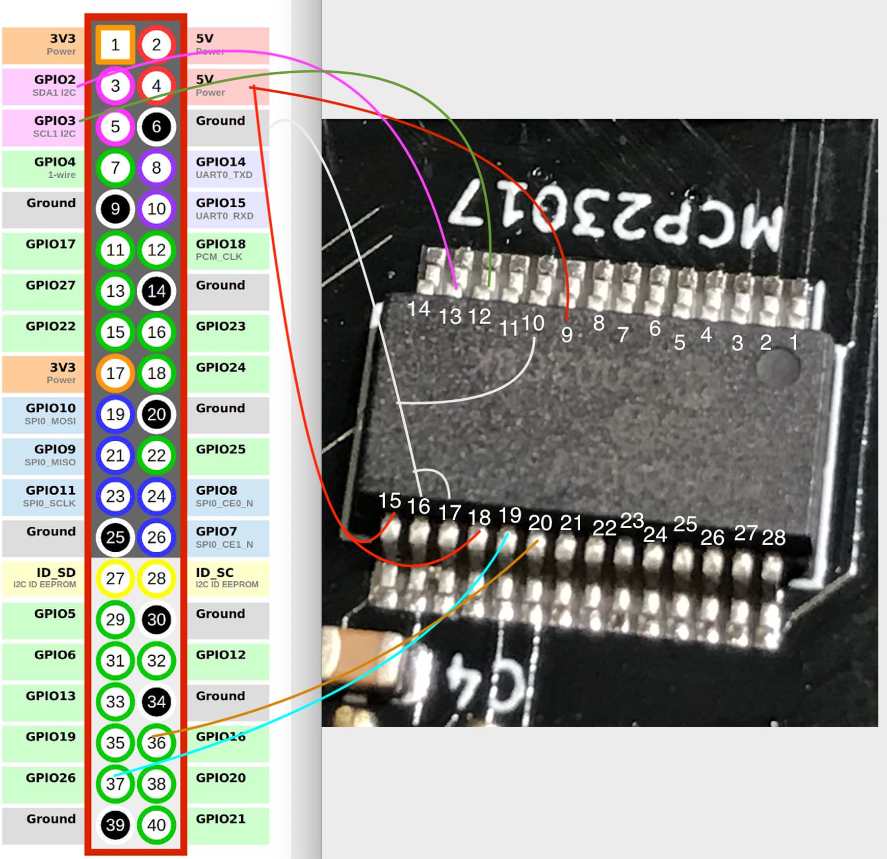
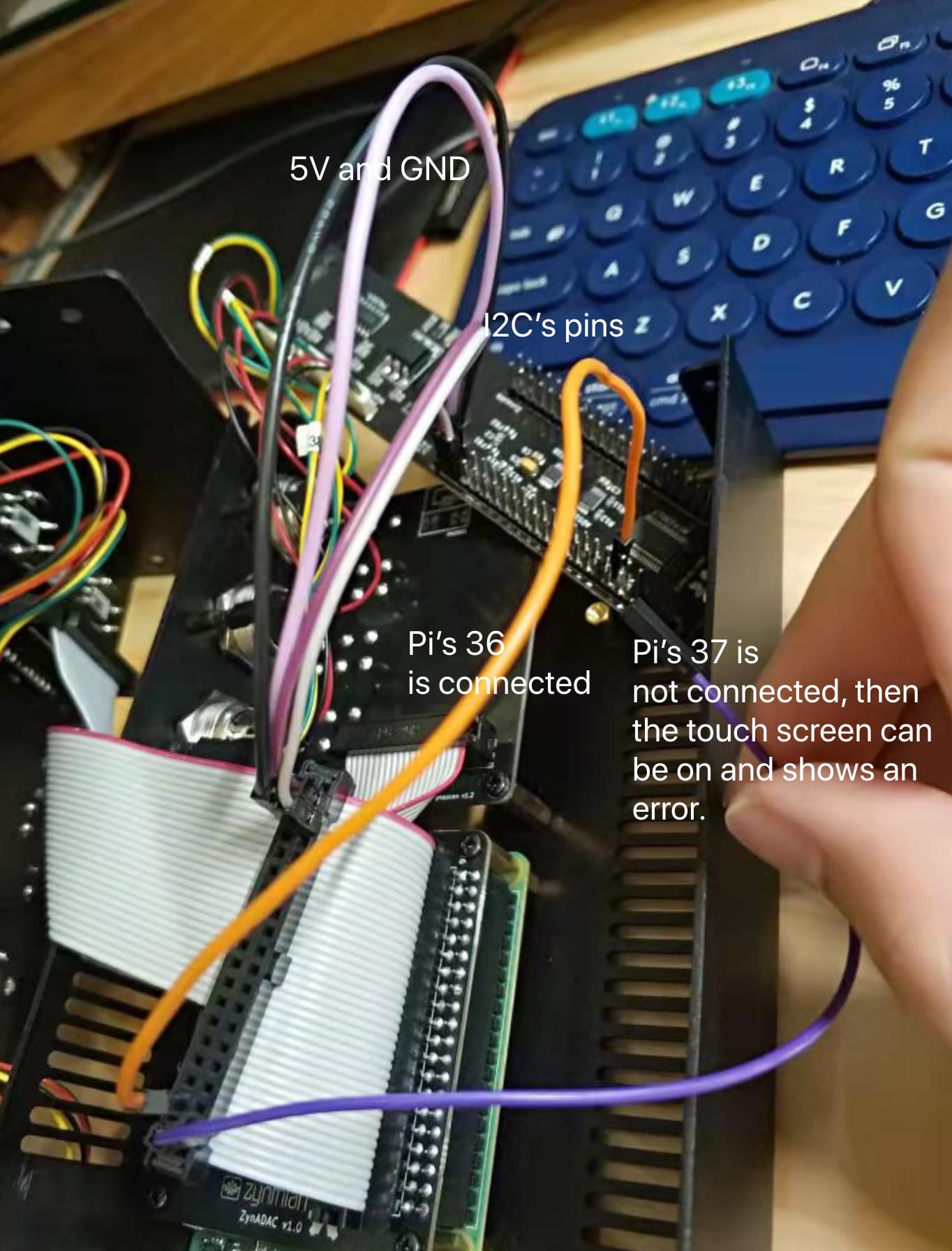
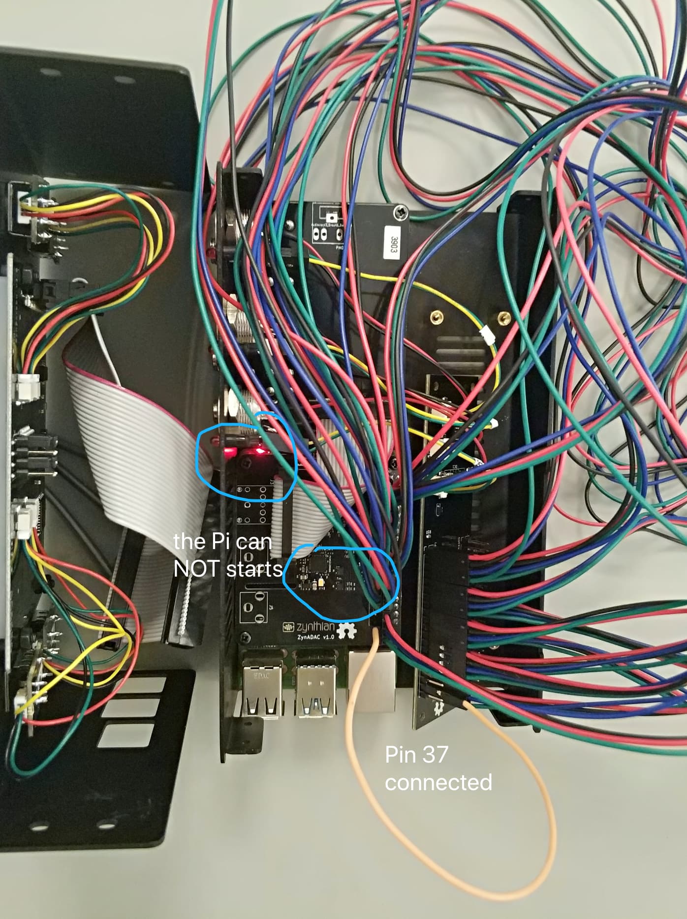
And then, I used jumpers rather than 40pins ribbon cable, connecting to the Zynaptik module.
It turned out… if Pi’s 37 is connected to the Zynaptik module, the problem occurs that the red LED is on while the green LED remains off, and the touch screen has nothing.
It could be the zynaptik. It could be the ribbon cable too. From time to time we have wrong units. We check for continuity every cable, but we don’t check for CCs. If you don’t find the problem, I would send you a replacement ASAP.
Pin 37 is INTerupt B which is connected to PIn 19 on the chip so that’s ok.
If we don’t see a short to ground on the Power supply that’s good news.
It’s beginning to sould like the problem could be elsewhere.
Does the Pi start up with just the ribbon cable connected.? You say replacing the ribbon with wires works if you don’t connect Pin 37? The problem seems to be certainly around that pin. Can you check to see if Pin 37 is shorted to either +5V or 0v as well as connected to pin 19 0n the chip?
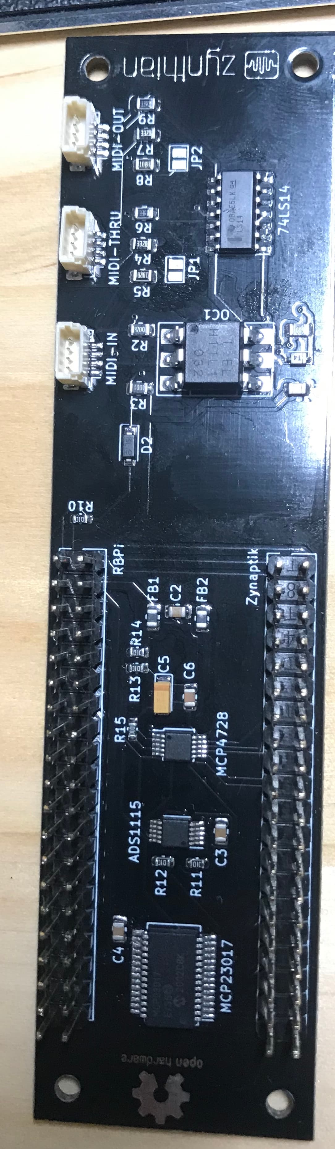
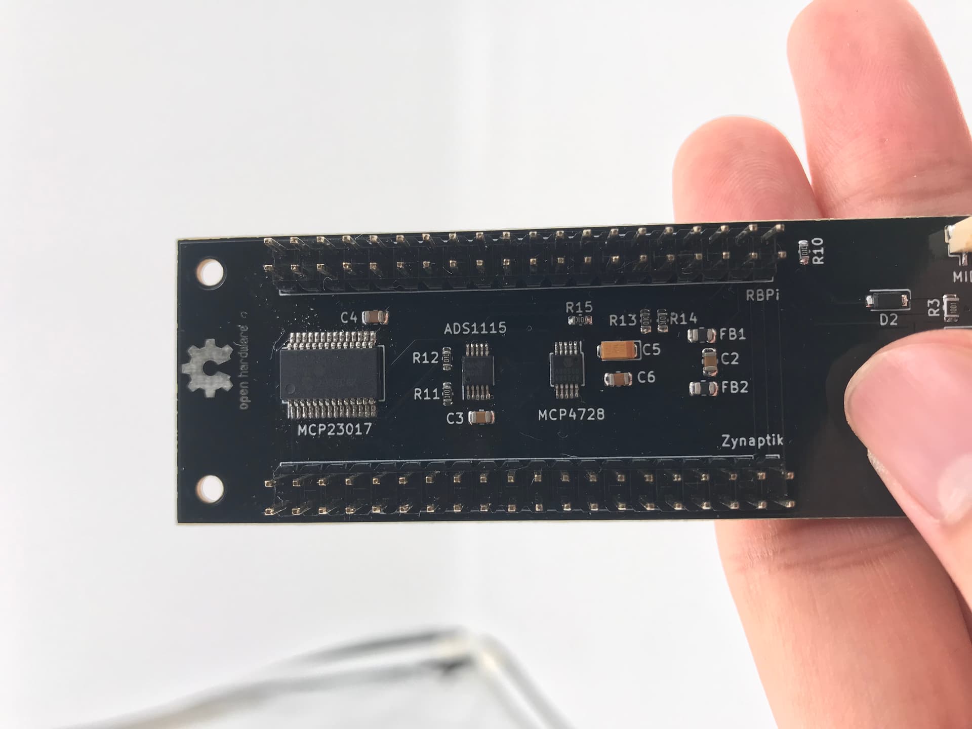
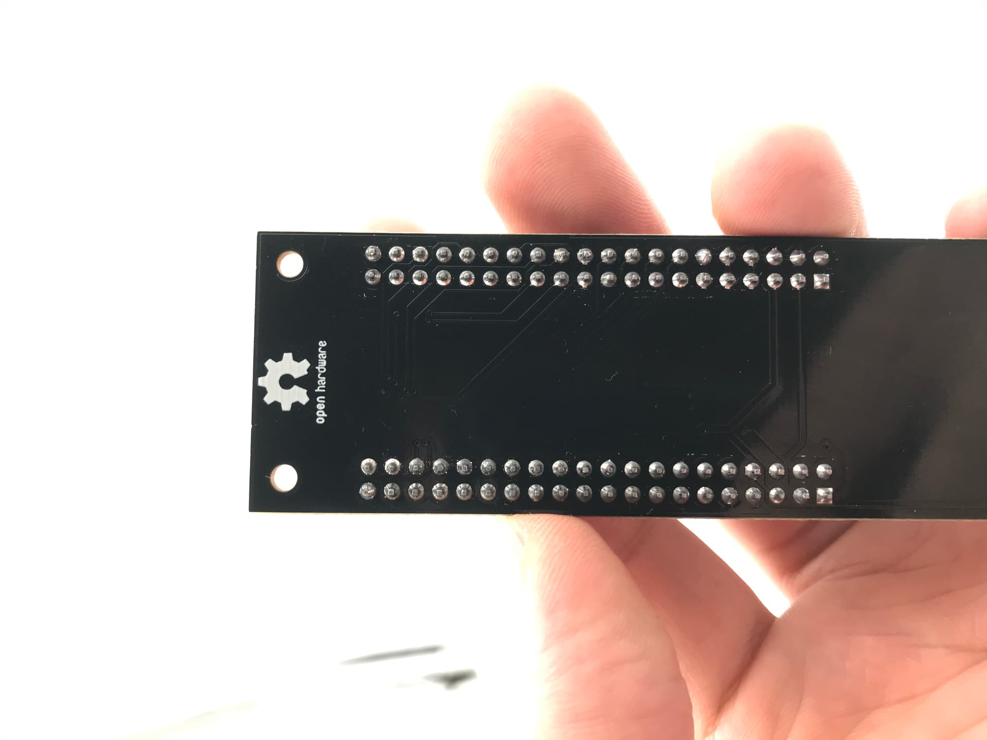
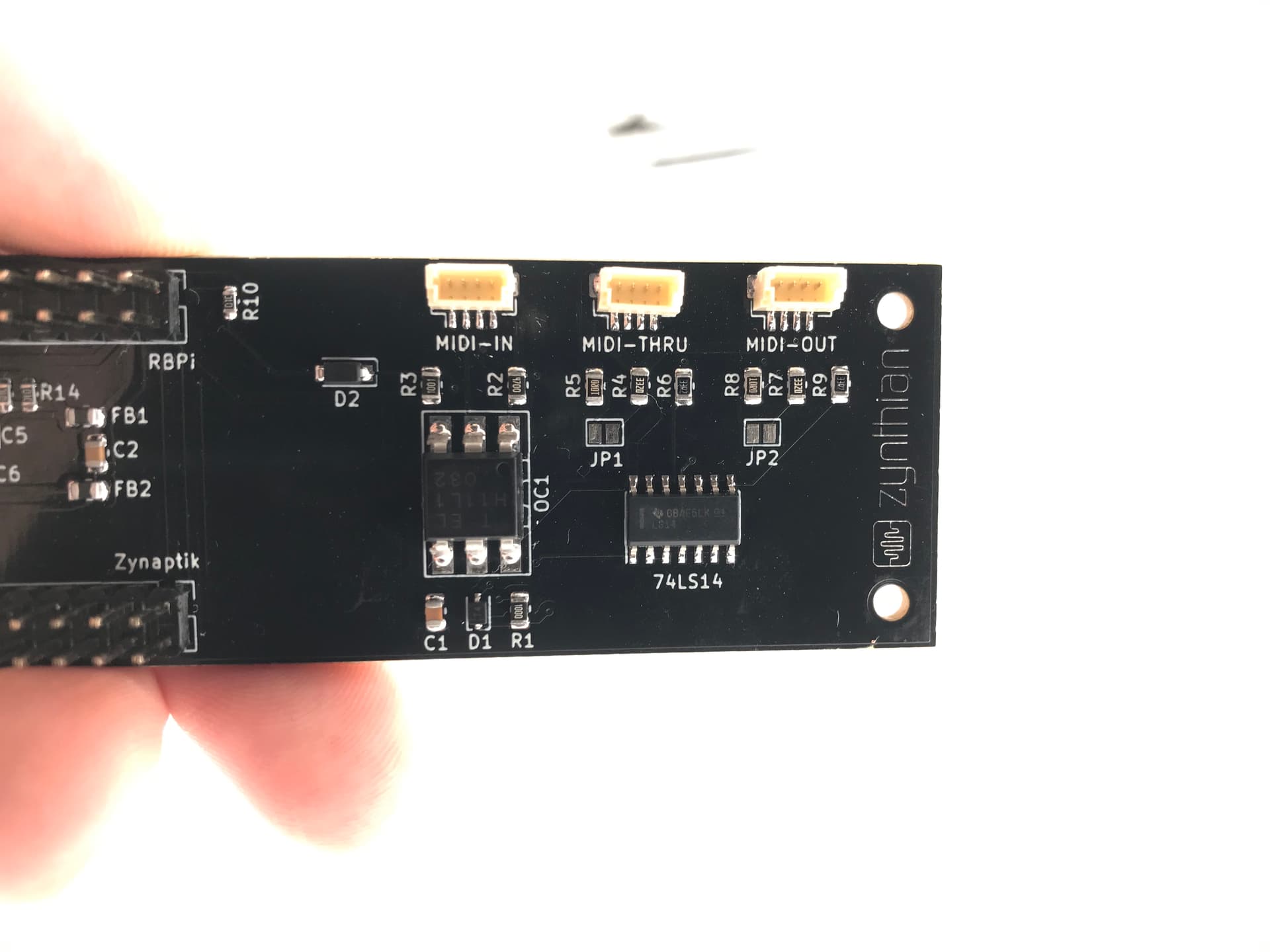
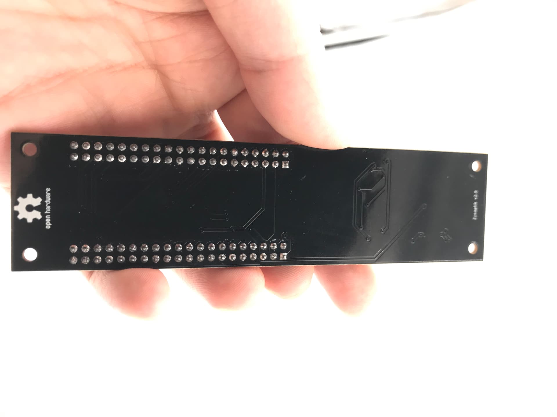
IT’s a great picture of the chip but could you take square on pictures of the front and the back of the zynaptik board? especially around the connectors ?
yes, as long as Pin 37 is connected from Pi to the PCB, the Pi can’t start properly in a way that only the red LED is on while the green remains off, nothing shows in the touch screen.
I checked:
Pin 37 is not shorted to either +5V or GND
Chip’s 19 is not shorted to either +5V or GND
Strange… what may go wrong…
Here are pictures of the PCB, its appearance looks fine to me:
I just did another test that can rule out the ribbon cable as being a possible problem:
I disconnected the touch screen from the HifiBerry soundcard’s 40 pins and put the part aside.
I used many female jumers connecting 40pins apart from pin 33, 35, 37, 39 to the Zynaptik module, and the Pi can start properly as the red light on, the green led flashes.
No obvious solder bridges.
Unless pin37 is misconfigured in the zynth Ian setup I can’t think of what might be causing this other than a fault within the 23017.
The error log of the zynth might contain some details but presumably it fails to start up the 12c infrastructure in such a circumstance.
What voltage is on the line when it fails to start up? Is it constancy 5v, 3.3v or 0v.? It should be +v going to 0v when an interrupt is signalled.(at least that’s my understanding) the function of these lines is to inform the pi that the mc23017 has received an event that triggers an interrupt. This is all made a little ilbit more complicated by the 3.3v/5v translation of the bus. Gpio Pins on pis shouldn’t be exposed to 5v. You might have a damaged pi on this specific pin if it’s been at 5v for instance.
A small test circuit with an Led and a 1k resistor might see if there is any actual signal on the line and this could be used to test whether or not the pi pin is still a going concern.
Do you get continuity from the gpio pin to the pin on the mcp23017 pin with no power on?
Is there any signs of issues on pin 37 at the pi end?
 !!!
!!!


