The good news is that the Zynthian is totally working fine so long as I “mainline” a USB-C power cable directly into the Raspberry Pi itself. I’m using a cable that I specifically got for an RBPi 4 Zynthian setup before I had the v5.1 kit. My Friday gig went without a hitch (at least no problems on the technical side; I can’t blame the unit for me starting one of the songs in the wrong key! ). So this was very helpful to know that the entire unit, not just everything directly on the Raspberry Pi, will function when powering just the RBPi, including even the monitor.
If anyone has any other suggestions I’d greatly appreciate it. Thanks again for everyone’s help.
The issue could also be due to the solder joint connecting the power input to the PCB.
Solder Joints, especially lead-free Sn99 connections, break very easily under mechanical stress.
Special alloys such as Sn96Ag3.7Cu0.3 are somewhat more resilient. It is never advisable to solder connectors directly to the PCB without providing additional mechanical support at the housing. While there are PCB design techniques that can make connector solder joints significantly more robust, these are taught neither in schools nor at universities, and many “professionals” have never even given them a thought… 6k cycles are nothing for the service life of a switch…
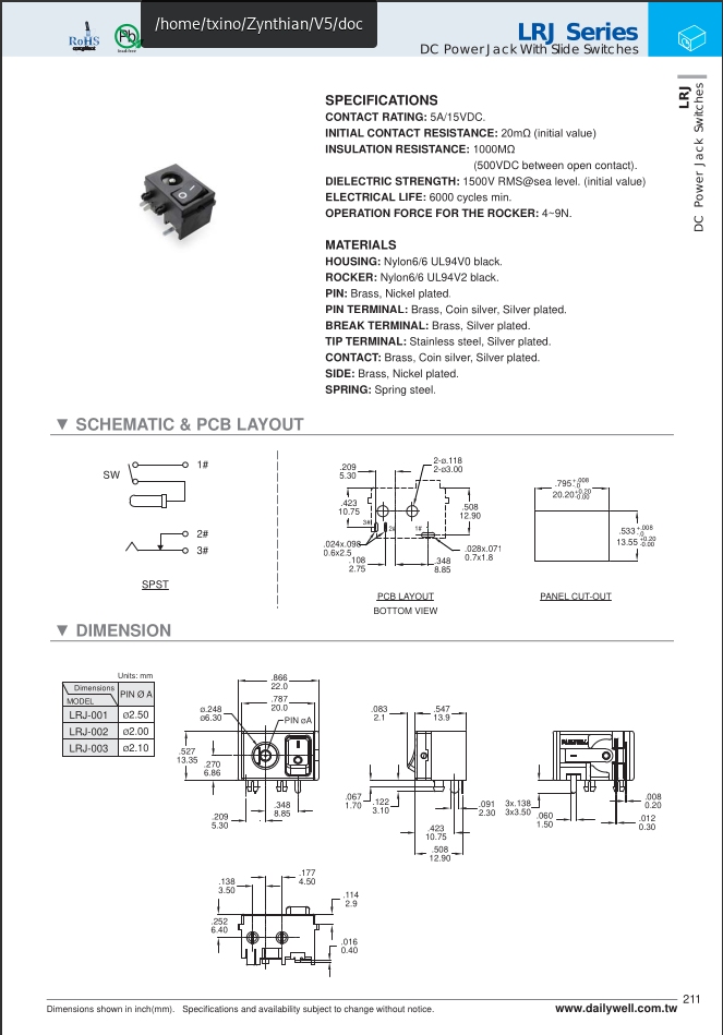
The LRJ series is a good quality component (for the tiny size) and have additional mechanical support (2 “big” plastic inserts) that avoid too much mechanical stress in the soldered pins.
I doubt it’s a soldering issue, but anyway, checking this is very easy, so please, @tkc, take a look at the switch pins to ensure they are firmly soldered to the PCB.
For the curious, the decision of using this part for the V5 mainboard was not a fast and semi-random one. You can’t buy this component in mouser, digikey nor aliexpress, etc. We buy and import directly from the manufacturer in Taiwan, what normally causes headaches and extra costs. We spent a nice amount of time looking for the right part until we find it!
IMHO, the most probable causes are:
Mechanical failure of the switch or barrel connector. This can be easily checked with a multimeter.
Electrical failure of some component in the mainboard’s power circuit. It could be:
A capacitor. Electrolytic ones use to be the habitual suspects.
The power converter IC (SIC478) => This would be the worst case, as it’s the more expensive and difficult to replace.
Since powering the Pi directly makes the whole unit work, the quickest split is to test the 24 V path with the unit unplugged first: continuity through the barrel socket and the power switch in both switch positions, and a gentle wiggle test while watching for an intermittent reading. If a repair shop has a multimeter, I’d also ask them to measure the voltage at the board input while switching on, not only with no load; a cracked joint or failing contact can look fine open-circuit and collapse under load. A close photo of the socket and switch solder side may reveal a ring crack, but I would avoid probing the live board unless the technician is comfortable with it. The direct Pi supply is a good temporary gig workaround, and the symptoms now narrow the fault to the input/switch/power-conversion path rather than the Pi or display.
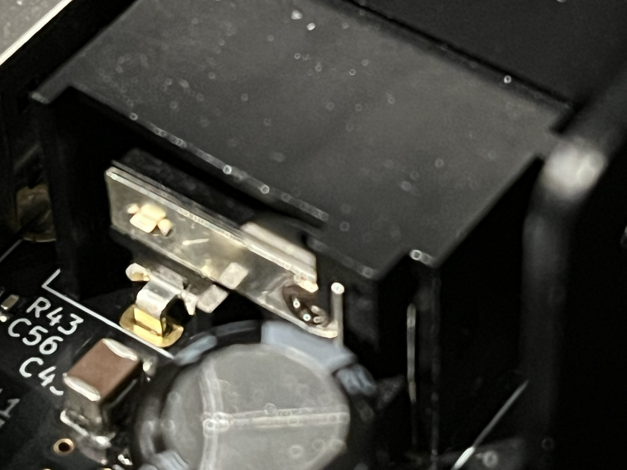
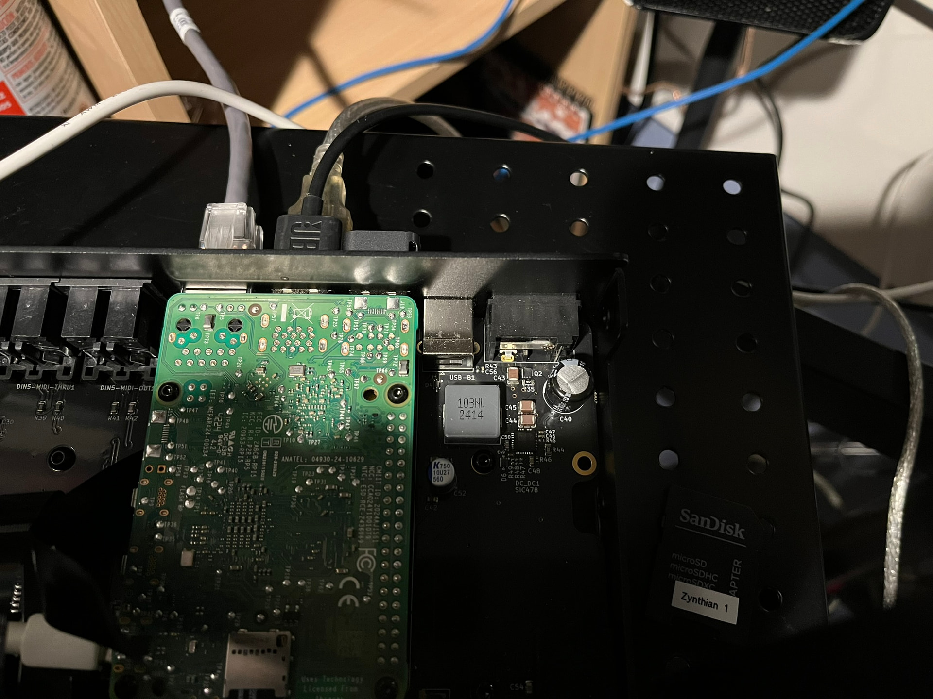
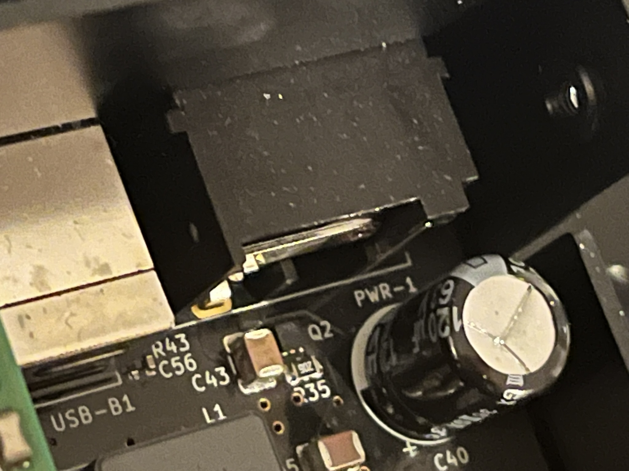
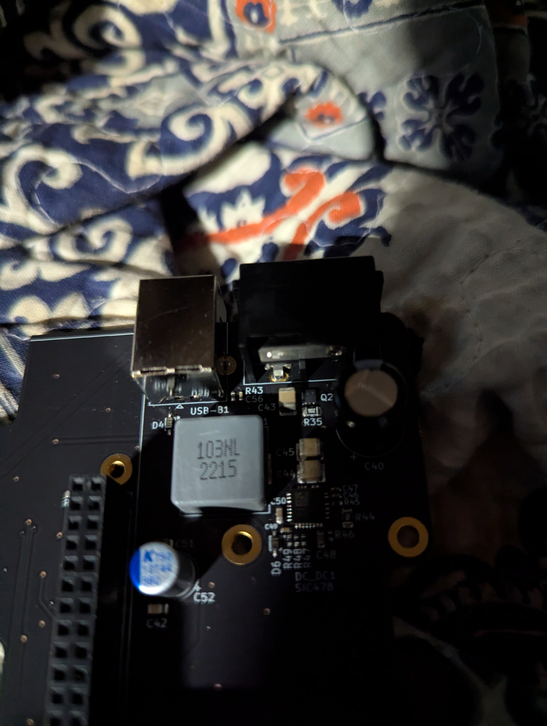
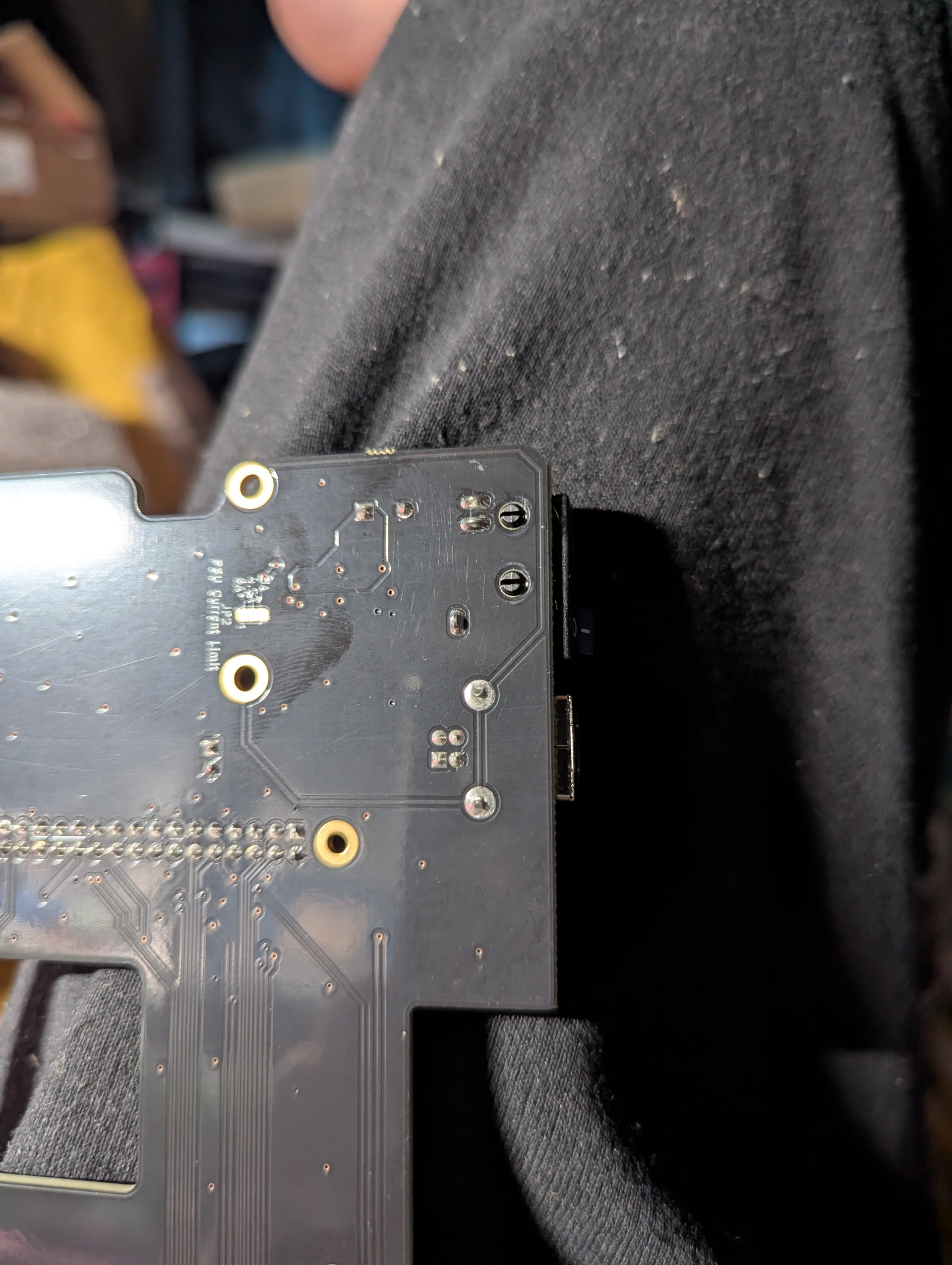
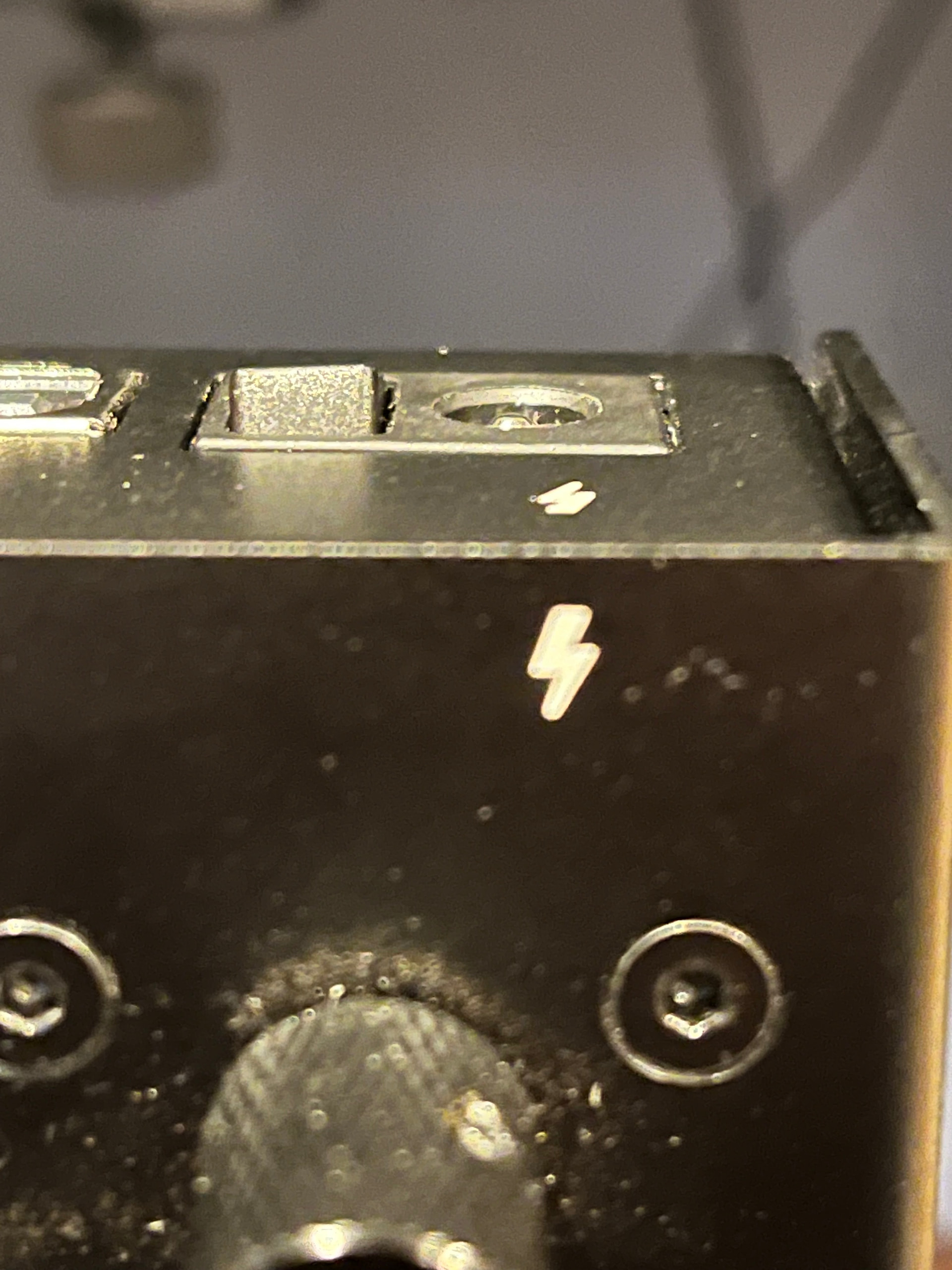
Thanks everyone for your input. Probably a dumb question, but I’m guessing that in order to check the solder joints to the power switch, I will need to disconnect the control board from the chassis so I can look underneath where the switch connects to the unit. I’ve attached the best pictures I could take of the switch before I do this:
Also, I took a movie of the actual behavior of the boot. I always had the case closed when I booted it up before, but looking now I see that the RBPi is receiving continuous power, but something causes it to go from a green LED for a few seconds to a continuous red LED. I am wondering whether this is significant:
Yes, except I think you mean the Main Board, not the control board, since the Main has the power inlet.
On a Main Board here, I can actually see some solder on that big metal tab just above and to the right of the R43 label, unlike yours. but the key is whether you see good, smooth solder joints on the bottom side of the Main Board.
Thanks @tunagenes for the photos, this is very helpful! I hope it is something that simple. If I don’t see any obvious disconnects between the switch and the main board, I’m probably out of my depth to troubleshoot any further. I’ll try to get to it this weekend.
The pin 1 (the single one) under the power inlet seems to have a beginning circular crack around the pin in the meniscus of solder. I’d keep an eye on that one. The PCB is not the one of thread starter, right?
The solder joints with the two clipped wires give me the vibes, too. It is never good to clip a pin after soldering lead-free, because the additional stress on the solder joint makes it less reliable in the long term.
Alright, I’m about to remove the main board from the Zynthian so I can inspect where the switch connects to see if there are any cracks (I’ll take plenty of photos). I’m pretty nervous, as the unit is working today and I rely on it quite a bit, so hoping not to mess anything up worse! I’m assuming I should follow these steps, unless anyone has any other suggestions:
Disconnect the display flat cable from the monitor/display. Open the display’s FPC tongue with two fingers (one from each hand), then slide the cable out.
Disconnect the CONTROL-1 cable from the main board. Open that connector’s tongue and pull the ribbon free.
Remove the 2 screws on the case underside — the thermal block mounting screws.
Remove the 7 main board screws holding it to the case bottom.
Lift the main board out, with the RPi5, thermal block, and SD/USB-C adapters all still attached as one unit.
If I hold that switch down flat by applying pressure, the Zynthian boots.
Is the only solution getting a new switch and replacing it? Or is it safe to just put a little more pressure on that switch to get it to sit flush so it maintains a steady contact?
The part is not easy to find. I would send you a replacement. You look for someone with the required skills and tools for replacing the part clean and safely. Here in spain we have a lot of “mobile repairers from pakistan” that usually can do the task. I don’t know how this work in your town.
Thanks @jofemodo, I really appreciate it! I’m sure I can find someone who can do the repair here. Please let me know if you still have my address on file and if you have any questions.
 ). So this was very helpful to know that the entire unit, not just everything directly on the Raspberry Pi, will function when powering just the RBPi, including even the monitor.