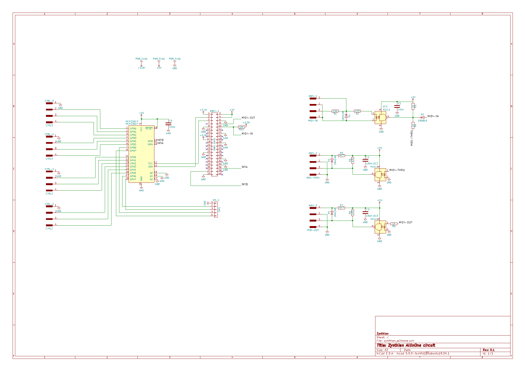
and noticing that the LED connects to pins 3 (cathode) and 4 (anode) of the MIDI-3 header and looks like it would only get forward biased (turn on) if the output of OC3 goes below gnd, which doesn’t seem likely. Even if the build instructions are simply incorrect and the anode and cathode are switched, shouldn’t there be a resistor to control the current through the LED? Finally IIUC the LED should turn on when the midi-out signal is high, which will make pin3 of MIDI-3 to go to gnd. So for the led to activate pin 4 must be tied to 3 or 5v. The same is true of the midi-thru circuit. This only affects the LED operation, so luckily its not a big problem for those who already have boards.
So I propose that pin 4 of MIDI-2 and MIDI-3 should connect to a 100 ohm resistor which is tied to the 5v rail.
It’s of course possible I’m getting it wrong too though.
It’s not a voltage out as much as a current sink.
The 470 Ohm resistor provides the current when the LED is on i.e. current is flowing from the +supply rail to the ground via the LED, so it turns on.
When the output is enabled in effect the LED is shorted out by the open collector output darlington turning on.
You don’ turn on a voltage down a MIDI Line you short it out the circle on the Output means logically the output is inverted so NO LED when no data moving.
At least that’s my understanding.
I spent a busy week having bought open-collector outputs in TTL and not understanding why they didn’t work logically.
I’m not an expert, but i also have theories about it … jeje!
As @wyleu has told above, MIDI transport work as a current loop. For avoiding ground loops, the MIDI-IN ground must be “floating” (as it’s in zynthian’s MIDI-IN circuit), and should exists a “flyback” diode (or something similar) that allows reverse currents that occurs during commutation. These reverse currents cause that voltage in MIDI-OUT/THRU pin3 can be negative, because of these reverse currents.
Zynthian MIDI-OUT/THRU activity LEDs use these small reverse currents, re-using part of the current loop energy for signaling the activity, and avoiding the use of “fresh” energy and extra circuitry.
The result is that LED light is quite low, but normally it’s enough for our use case: knowing if there is MIDI activity
I’ve not made a detailed analysis nor simulation, so i could be totally wrong. This circuit is a contribution from a Zynthian community member (@Imager) and perhaps he could give a better explanation.
 the circle on the Output means logically the output is inverted so NO LED when no data moving.
