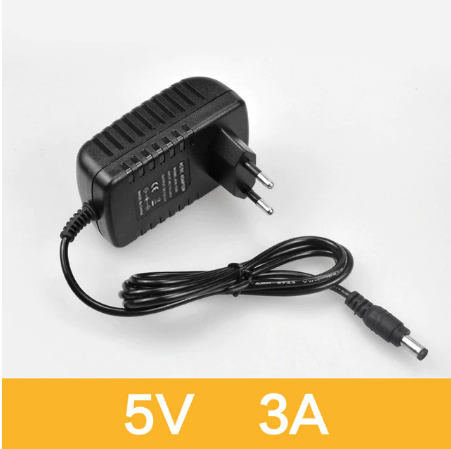
I would like to build a different DC Power Input. I would like to do it with this male Plug:; link
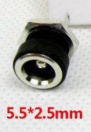
And I would like to use this female plug:
I’m not shure about the connecting.
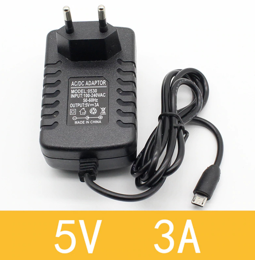
The easy way is to solder a micro USB to the DC Power supply and plug in into the Raspberry (no female Plug required).
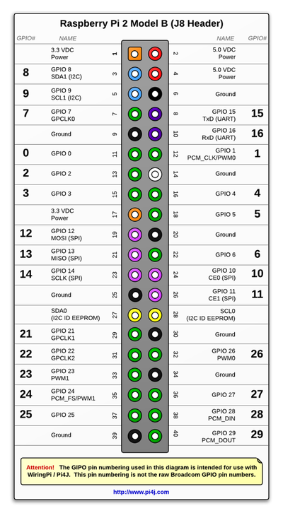
But I would like to have a alternate power input with direct connection to the Raspberry. I read this site ( click me )and think i can connect the new input direct to the GPIO PIN 2(+) & 4(+) & 6 (GND/-). Do i need to power PIN 2 and 4 or is one enough? GPIO Pins
Am I right or will i damage my Raspberry? Do i need a safety Diode and if yes why? What is a ZVD Circuit?
If anyone has a better idea i’m very interested knowing it
A ZVD (Zero Voltage Diode) is a circuit that behaves like an ideal diode (a diode with zero voltage drop).
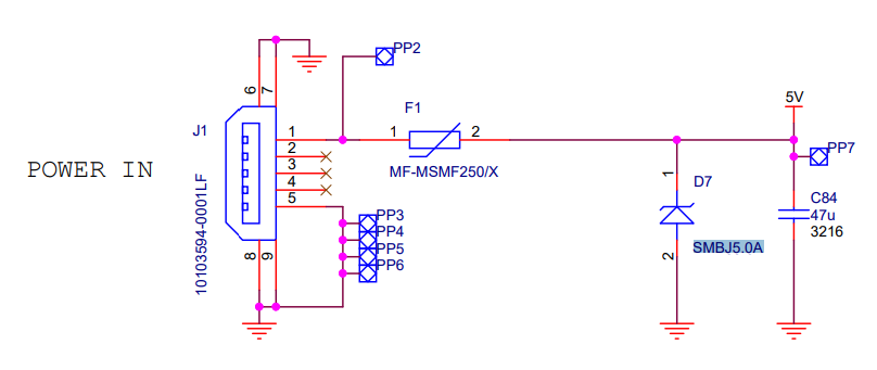
Powering through the GPIO connector is not a strange thing. The pins marked 5V and GND are connected to the USB power input. ( look at the schematics )
If you don’t know what you’re doing, then you need a diode.
And if you need a diode, it must be a ZVD, because even the 0.6V voltage drop on a normal diode junction will render the rPI very unstable.
In the Zynthian I built, I used a similar connector on the rear case panel with a short cable from the connector terminals to a micro USB male connector.
thank you for explanation.
The ZVD is for safety because of over- and undervoltage? or is it to be safe about mix up + and GND?
Here is quote from another site: (I use a Raspberry Pi 3B+)
NOTE that the Raspberry Pi 3B+ and Pi Zero and ZeroW do not include an input ZVD. The micro-USB input on a Pi is expected to / almost universally is driven by a power source which does not sink current, i.e. it will not try to actively pull down a voltage higher than its regulated voltage. If a HAT back-powers a Pi and uses a power source that does not try to sink current (and will safely stop/pause regulation if its input voltage is higher than its regulation voltage) it is OK to not include a ZVD on a HAT. If you are unsure or don’t know then please include the ZVD!
This means if my power input is safe with over-and undervoltage i don’t need a ZVD?
What is the meaning of this quote: If the add-on board uses any more GPIO connector pins than the first 26 and provides back-powering via the 5V GPIO header pins it is required to: 1. Implement a duplicate power safety diode before the HAT 5V net (which then feeds power back through the 5V GPIO pins) as shown in this diagram. Alternatively provide some other mechanism to guarantee that it is safe if both the Pi PSU and add-on board PSU are connected. It is still recommended to add this circuitry for new board designs that only implement the first 26 pins of the GPIO header but that also implement back powering (see below note) 2. Make sure that the supply that does the back-powering can supply 5V at 2.5A.
Now i found out the HIFIBerry has 5V Pins. They are somehow connected to de GPIO Header. I couldn’t find a schema, just this information from HIFIBerry: click me
If i don’t de-solder the resistor i can use it to backpower the Raspberry?
I also read about linear power supply. Is this needed or just a bit better than my first choice of power supply? example product or better this?
In this context, the diode avoids the “conflict” between two power sourcers when you power the board from USB and from the GPIO connector AT THE SAME TIME. Ok, it will also avoid polarity errors, but this should not be an issue in a DIY device (I mean, if you can burn the card twice in that way, you deserve it )
So, if you’re absolutely sure that you’ll never EVER plug another power source into the rPI while it’s powered from the GPIO port, and that you’ll never plug your supply backward, then you can go without diode.
When I read the word “audiophile” my bullshit meter gets instantly overloaded. One day I’ll write about my fantastic audiophile grade (i mean REALLY EXPENSIVE) shielded heavy cables and my ban from more than one local audiophile community )
But hey, who am I to keep you from spending 50€ or more for a less-than-10-euro power supply?
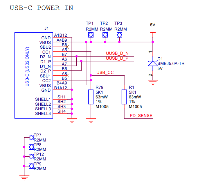
Using the GPIO connector you’re actually powering the rPI from the “5V” point. Doing so, you’re rendering the protection (resettable fuse MSMF250X and transient suppressor SMBJ5.0A) useless.
I have an issue with an internal meanwell power supply (6A).
I am using one of those MicroUSB wires, that are open on one end.
But with Raspi4 I added an additional USB-C adapter.
When I was using the officical raspi4 power supply, I don’t have any xruns with pianoteq.
But when I use this meanwell hack, there are a lot yellow flashes.
The Meanwell has two outlets. I use the second one for the keyboard adapter. @Axeman do I have to consider anything regarding shielding those two?
Has anybody seen a USB-C wire already, that shows the black/red wires?
Should I cut a good one? I don’t know, how USB-C looks like in the inside…still red/black?
Or should I go for the GPIO 5V?
@mheidt, the power matters on the USBC connectors are quite complicated. You SHOULD find the red VBus cable and the copper shield is the power ground, BUT many cables uses black & red for sideband data signals and again black & red for TX2 and RX2, so you can’t be sure. Moreover the power provided from the port must be “negotiated”, and with many chinese adapters the process don’t work, and the port limits power to 1.5A.
On the rPI4 (where there is no resettable fuse), with a reliable power supply, I’d use GPIOs.
… or a couple of big wires soldered to the supply rail test points

