Arduino instead of MCP23017?

  • i2cget -y 1 8 0 b returns lowest changed register +1 (I described it wrong in previous post)
  • i2cget -y 1 8 x w returns correct values both for switches and for encoders, as you described
  • registers are set correctly
  • webconf is set as in your screenshot

what am I missing? I was thinking 5v messed up the interrupt pin, I divided voltage with the resistors (btw, is it a bad idea?) for the interrupt and tried another pin, and it still doesn’t work.
Few times I got reactions of the UI, but I could not recreate it

Share your latest code and I will try it here.

Here it is i2cencoders.ino (8.0 KB)
It’s not the tidiest code at the moment, but at least it does what I described

You are still instantiating too many controllers.

static const uint8_t MAX_CONTROLLERS = 128; // Maximum quantity of controllers
Controller g_anControllers[MAX_CONTROLLERS]; // Array of controller objects

creates 128 controllers which exhausts the memory of the Arduino. You need to create just the 8 you need and them map them to the registers.

I rewrote it to create only 8 controllers (really roughly with a lot of hardcoded stuff at the moment) and it didn’t help. I still get all the correct values from the command line, but it doesn’t work with the UI
i2cencoders.ino (8.1 KB)

If that was a problem, why I was able to get values through command line? I thought it wouldn’t work at all if the memory was full.

Isn’t it somehow related to interrupt?

Do I understand correctly that interrupt should be high unless there’s some change in the controller, then it should get low for a moment, telling the master that it should send the request, and then again become high?
I’ve checked the voltage on mine, and for some reason it does not get back to high after the change…

zyncoder driver detects a falling edge on its interrupt pin so will respond when the Arduino changes its interrupt pin from high to low. zyncoder driver will then process all changes until the interrupt returns high. The Arduino should keep its interrupt low whilst there are unread changes. Each switch / encoder register read should clear the dirty flag for that switch / encoder. When all switch and encoder dirty flags are clear the Arduino should return its interrupt pin high. So the interrupt pin should go low when you change an encoder / switch value and go high when all changes have been read by the RPi.

That’s more or less how I imagined it.
So, in theory, if I, for example, pushed a switch once, it should get back high almost immediately?
I guess my problem lays somewhere here. Thanks, I will continue to investigate stuff related to interrupt…

I’m slowly getting there. At some point it started working, but in a weird way. 2 encoders (first and second, if I’m not mistaken) were affecting bottom-left parameter in the UI (I was testing inside the layer, and both were affecting the same param). One was switching instantly from 0 to 127, another was switching slowly with the delay and was continuing to change value even after I stopped touching the encoder. Other encoders and switches didn’t affect anything. It worked like this a few times, but after a few reboots it stopped and only occasionally I was able to reset one of the parameters to zero and sometimes switch to the last element in the menu, but it looked more like an error than a rule.

i2cencoders.ino (8.3 KB)

A few days ago I rewired everything on a breadboard, and reassigned and rearranged the pins in code. Today I accidentally uploaded previous code with wrong pins and found out that select switch works (it was actually the encoder, because of the messed up pins, but still)… the funny thing is, that the interrupt pin was also set to different pin in code.

So after some investigation I found out that select button worked with the correct code… and interrupt totally disconnected! It was always working when I pressed it, and sometimes it was triggering by itself. All other controls didn’t seem to react. After few reboots it stopped working. I think I’m starting to go crazy.

Any idea how to systematically debug it?

Me, trying to understand what’s going on my breadboard:

I have added a utility to GitHub to show interrupt activity and get values from the interface. ssh to the Zynthian then:

systemctl stop zynthian
wget https://raw.githubusercontent.com/riban-bw/I2C-Hardware-Controller/master/test/i2ctest.c
gcc -o i2ctest -lwiringPi i2ctest.c
./i2ctest

This should give you some diagnostics. It will print out each time the interrupt is triggered and display the value of the changed controllers. Press a key to exit (unless it is overloaded in which case you may need to ctrl+c.) It should sit idle until you press / release a button or turn an encoder.

1 Like

Here is an updated sketch which seems to work. I have only tested with my test program, not with a real Zynthian and you will need to repopulate the arrays of pins but that should be all.
i2cencoders.ino (9.6 KB)

  • I have fixed a few issues, particularly around the indexing of registers and arrays which was a bit muddled.
  • I have added auto configuration based on size of input pin arrays hence just the need to populate them with pins used on your MCU.
  • I disabled the fast scrolling 'cos it isn’t really working well.
  • Clear value after reading
  • I changed quite a bit of the debug output but commented it all out again.

I would like to add the multiplex stuff back in but that requires a bit of thought to allow it to work without multiplexing. Ideally I would like to fold all this back into github so a single code base covers multiple MCU.

1 Like

omg, you are my hero! :slight_smile: thanks a lot, it works as it should.
and thanks a lot for helping me figure all this stuff out. I’m not good at coding, but I’ve learned a lot doing all this

Pictures and :face_with_monocle: !!

2 Likes

as soon as I’ll fit everything on the breadboard into tupperware :slight_smile: wait for me in success cases

1 Like

You do realise that involves a whole raft of paperwork and equipment moves…?

People will be flying off the battlements for this I can tell you . . .

1 Like

I’ll be prepared :face_with_monocle:

Here’s a wiki friendly write-up of what’s going on, as requested by @wyleu :face_with_monocle:. But it might also need some comments and clarifications from @riban. I’m describing this the way I have it connected now, without considering the matrix connections, which @riban said he’d like to introduce.

Pro Micro (and other Arduino boards) can be used to interface the encoders to Raspberry Pi using I2C protocol, plus act as a USB-MIDI device (this one is true only for ATmega32U4 based boards, such as Micro, Pro Micro and Leonardo)

Here’s how to wire the encoders, Pro Micro and Raspberry Pi, but other boards should follow more or less the same pattern

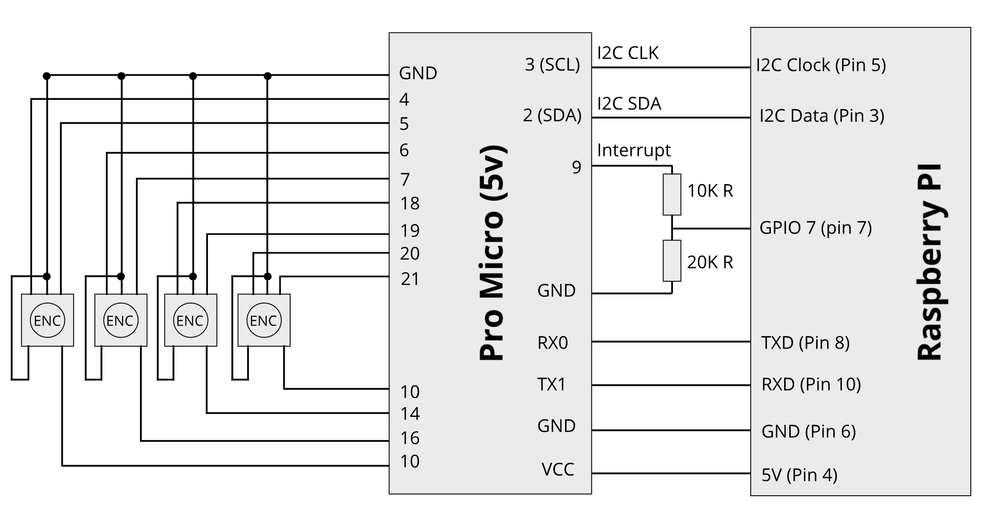
The encoders and switches should have common ground and connect to Pro Micro pins defined in the code. It’s easy to change pin numbers if you use other board, or want to connect in the other way.

I2C Data and Clock pins are on different pins for each board, for Pro Micro they are pin 2 and 3, and they should be connected to corresponding pins on Raspberry Pi.

Interrupt pin is also defined in code on Pro Micro side and in Zynthian webconf on the Raspberry Pi side. You can change this pins however will fit your setup better. Please note that if your board uses 5V logic signals, you should connect Interrupt using voltage divider, as shown in the diagram (can anybody confirm if using this 10K and 20K is ok? I mean it works for me, but is it the right approach?). Some Arduinos use 3,3V signals, in this case there is no need in resistors, and pins can be connected directly.

Connecting serial port RX and TX pins is needed only if you plan to use Pro Micro as a USB MIDI device. If your board can’t be used as a MIDI don’t connect them.

And connecting VCC and GND is how the board will be powered. If you use other board, check the power requirements for it, you might want to use Raspberry PI’s 3.3v output, or regulated input on your board.

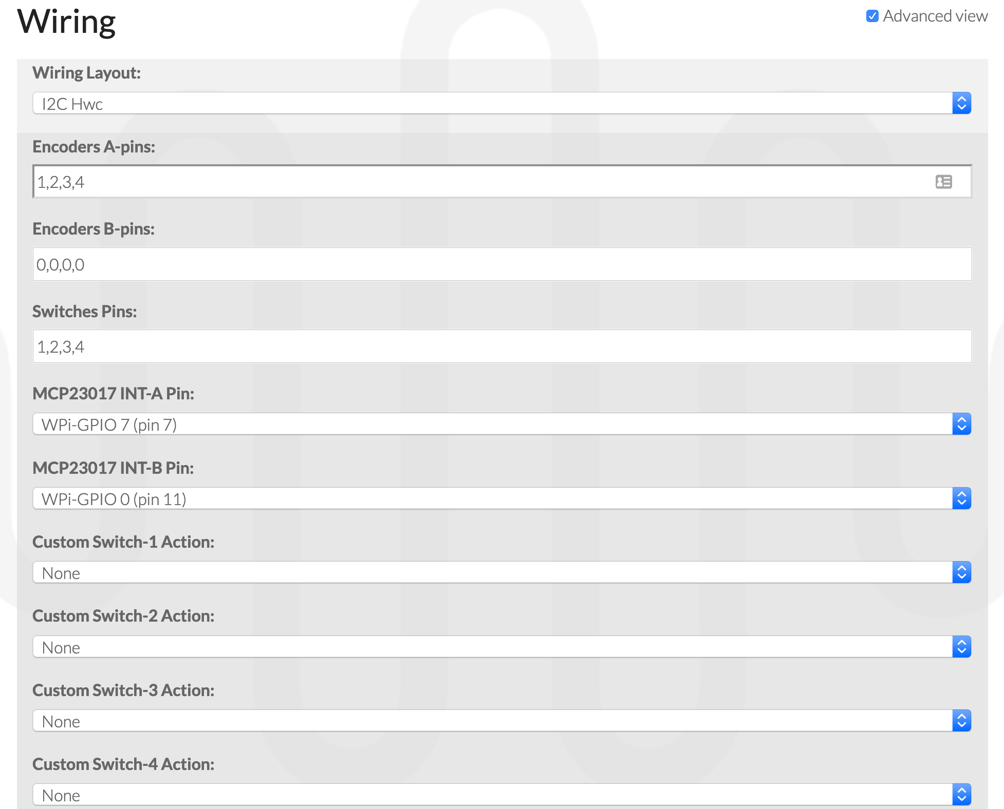
After uploading the code to the board and wiring everything up it’s time to power up the Raspberry Pi, go to webconf and set up the wiring. You can ignore the Encoders B-pins and MCP23017 INT-B Pin fields, only A-Pins matter here.

Here’s a small bonus. If you use board as USB MIDI device, you can rename it, so it will not appear as Arduino Pro Micro in the MIDI devices list

Here’s a sample of bassline from JV/MDA JX10 sequenced from Ableton through USB MIDI while playing with cutoff and resonance using encoders

Also here’s the code that I use at the moment, which actually adds USB MIDI stuff. zynthian-i2c-encoders_usb-to-serial-midi.ino (10.2 KB)
The only problem is that for some reason it transfers everything on one midi channel. I’ll look into fixing it later, and might host it on git, so it’s possible to link to it from wiki

10 Likes

Thanks that’s really nice.

Thanks, it worked for me :smiley:

2 Likes