Hey! Just wondering if it would be possible to use arduino-like board to wire up encoders? I know it’s probably an overkill, but I didn’t find any MCP23017 in local online stores, but I do have a couple of pro-micro laying without use.
Did anybody try something like this, or is it a crazy idea? Should I just order MCP23017 from China and wait until it’s shipped? Am I missing some other options for wiring up the encoders?
1 Like
@sleepy it is perfectly possible to use Arduino. I manage this project which uses an STM32 microcontroller to provide many encoders but the four required could probably be done with an arduino with minimal changes to firmware.
3 Likes
Sounds great. I think I’ll try to adapt to pro micro it if I won’t find simpler solution. Thanks!
That should be fairly simple  . I did adapt the code to run on a nano recently, and it did take a while to take out the extra multiplexing stuff. I can give you some advice if you like. I can dig out the code for that.
Thanks! I’ll dive into it this weekend, I guess I’ll have some questions then
@riban well, I do have some (probably stupid) questions now 
I’ll start with the software: arduino ide gives me an error that it could not find Wire_slave.h Is it part of some library I need to install?
As for the wiring, I came up with scheme like this:
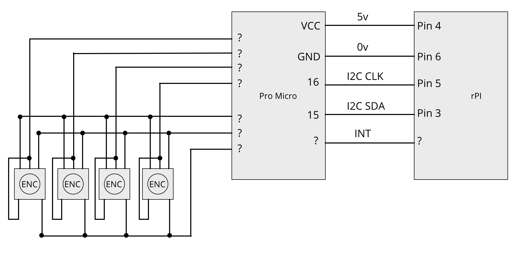
The questions are:
- where can I define the input pins for encoders? I didn’t find it in the code…
- is this 4x3 matrix correct? do I need to add diodes here?
- how to connect INT, and are CLK and SDA shown correctly?
Also seems like the comments in the code for #define SWITCHES and #define ENCODERS switched places
ok, now I’m confused a little more. There should be 2 INTs? A and B?
Sorry what I mean is where you have the ? ----INT— ?.
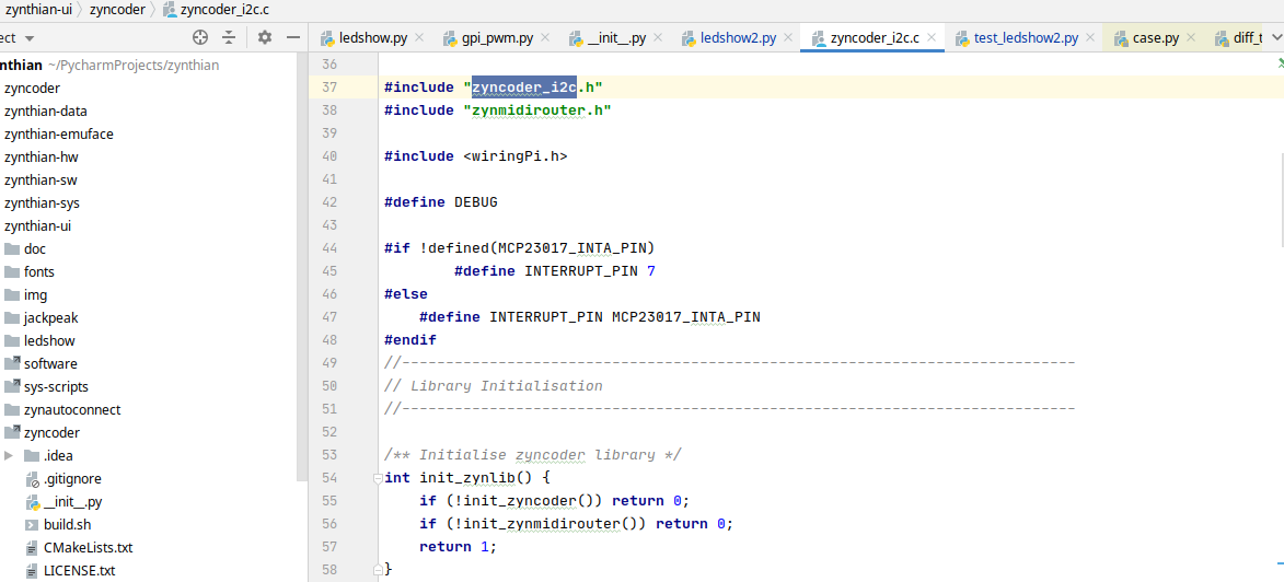
at the synth end it’s handled by this code. . .
1 Like
Hi @sleepy
You will need some signal diodes, e.g. 1N4148 between each encoder pin and the ProMicro. Anodes should be connected together and connected to the Pro Micro. Cathodes individually connected to the encoder pins. Similarly you need diodes between each switch pin and the PorMicro. Again, Anodes connected together and to the Pro Micro. The common pins of each switch and encoder does not require a diode.
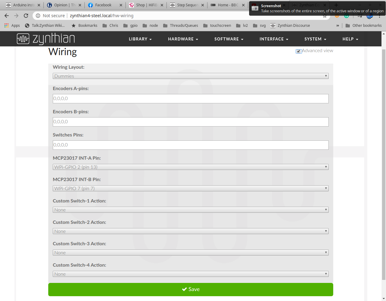
The webconf offers two interrupts which are used by the MCP23017 interface. I have not yet submitted a request for the webconf to be modified for the I2C interface so just use the first of these. So select the RPi pin on MCP23017 INT-A Pin in the webconf.
Similarly, use just the Encoder A-pins configuration to specify the encoder numbers (1,2,3,4 or whatever order you end up connecting them). And add the same configuration in Switches Pins. This relates to the I2C register number (minus an offset for switches / encoders). I would recommend using the first 4 registers. If you add more switches then you should be able to configure Custom Switch actions but I have not yet tried that. (Let’s walk first!)
Regarding Wire_slave.h, that is the header for the Arduino I2C library. If you are using the Arduino IDE then you need to install the library. Sketch->Include Library->Manage Libraries… (Ctrl+Shift+I). Then install WireData library. This library may differ slightly to the one I used in the STM32. It looks like the header is called Wire.h.
There should be enough info there for you to get on for a while. I am not sure whether I will have a chance to test this with an Arduino but if you get stuck then come back. I reckon it should work okay with 4 encoders.
Cheers
1 Like
I hope it is going well. One tip for when you get it working: The dynamics for slow / fast rotation need optimising. I meant to review after building but had many Zynthian woes so didn’t get round to it and now find it too easy to send +/-10 messages which confuse things… mostly me  . I don’t think the official encoders do this scaling so I may disable it until I have time to optimise.
At the moment I’m still trying to make it compile as it seems like Wire_slave.h and Wire.h are quite different and I get a lot of errors related to it. Did you say you made it work on arduino nano? Did you also have problems with this?
I made a single encoder decoding work on Arduino nano. I am sure it should be able to cope with 4 encoders. You may wish to ignore all the multiplexing and just wire all four encoders and switches directly to Arduino pins. This would require 12 input pins. You also need I2C (pins 4 & 5) and an interrupt output pin so that is 15 GPI pins in total. If there are insufficient pins then you would need to multiplex.
For I2C you will need stuff like:
setup() {
    ...
    Wire.begin(8); // I2C address is 8
    Wire.onRequest(onI2Crequest);
    Wire.onReceive(onI2Creceive);
}

/** @brief  Sends controller 16-bit value to I2C master
 *  @param  nValue 16 bit signed value to send
 */
void sendValue(int16_t nValue)
{
    Wire.flush();
    uint8_t data[2];
    data[0] = (nValue & 0xFF00) >> 8;
    data[1] = (nValue & 0xFF);
    Wire.write(data, 2);
}

/** @brief  Handle I2C request for data from master
 *  @note   Send the requested register (controller) value or index of next changed controller
 */
void onI2Crequest()
{
    if(g_nI2Cregister)
    {
        // Send value of requested controller
        sendValue(g_nI2Cregister);
        g_nI2Cregister = 0;
        return;
    }
    // Send index of first changed controller or zero if all clean
    Wire.flush(); // STM32 seems to need to flush I2C to ensure single byte of data is sent correctly - not sure if Arduino is same
    Wire.write(getDirty());
}

/** @brief  Handle I2C message from master
 *  @param  nBytes Quantity of bytes in message
 *  @note   Expects single byte containing the register address for next I2C read operation
 */
void onI2Creceive(int nBytes)
{
    if(nBytes < 1)
        return;
    int nValue = Wire.read();
    if(nValue == COMMAND_HEADER && nBytes > 1)
    {
        nValue = Wire.read();
        switch(nValue)
        {
            case CMD_RESET:
                reset();
                break;
        }
    }
    else
    {
        g_nI2Cregister = nValue;
        g_nLastRead = g_nI2Cregister; // Store last read register to allow getDirty() to find next dirty register
    }
    while(Wire.available())
        Wire.read(); // Clear buffer of unexpected bytes
}
2 Likes
thanks, I guess it will keep me busy for tomorrow and yes, wiring encoders directly to board seems like a good idea since i have enough pins
You can do that then if you want to add more switches you could adapt it to add the diodes and multiplex. I noticed that my code uses internal pull-down resistors which the StM32 has but Arduino does not. If you were to multiplex then you will need to consider the diode direction and pull up/down resistors. Get it working with simple code / hardware then consider enhancements.
1 Like
btw, I assume it’s not the whole code? I see it references some functions from the full version. Anyway I think I’m going to make it work
Yes - just snippets. I edited a cut-down version with these snippets and it compiled without errors but I have not uploaded to an Arduino. I was tempted but an knackered after a day of hard graft and many sleepless nights. Also, stepseq is taking all my time… Good luck and feel free to ask more questions. I would love to see the I2C interface used by more than just me  .
.
2 Likes
I’ve put together the code with that snippets and some parts of the original code but stripped down stuff related to matrices. Now I have the code that is compiling without errors, now I need to find a way to debug everything and find at which stage it fails, as it doesn’t seem to work
I’ve got it wired like this
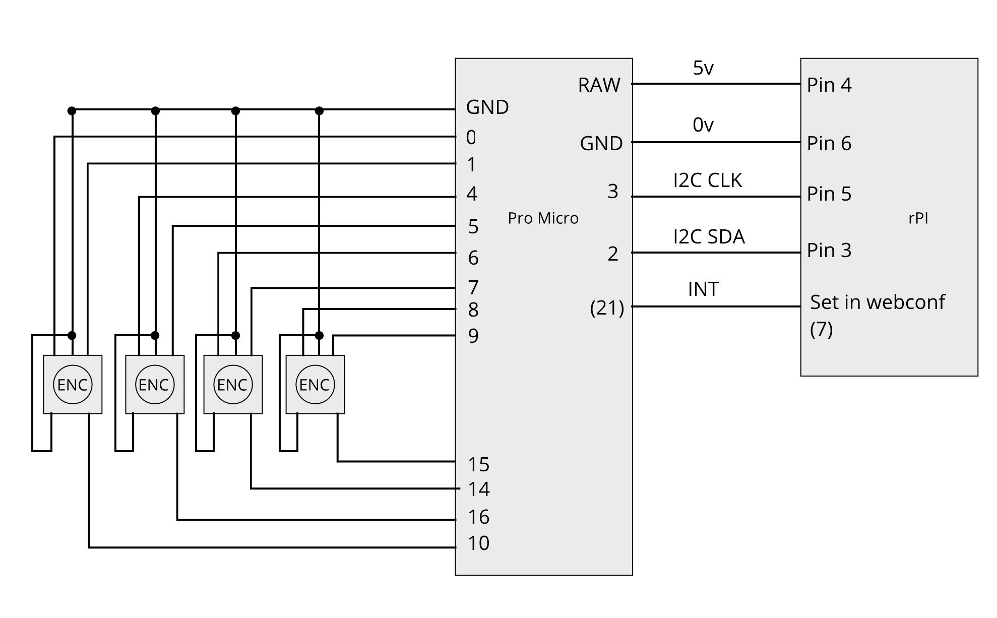
With this code i2cencoders.ino (6.9 KB)
And this in the webconf
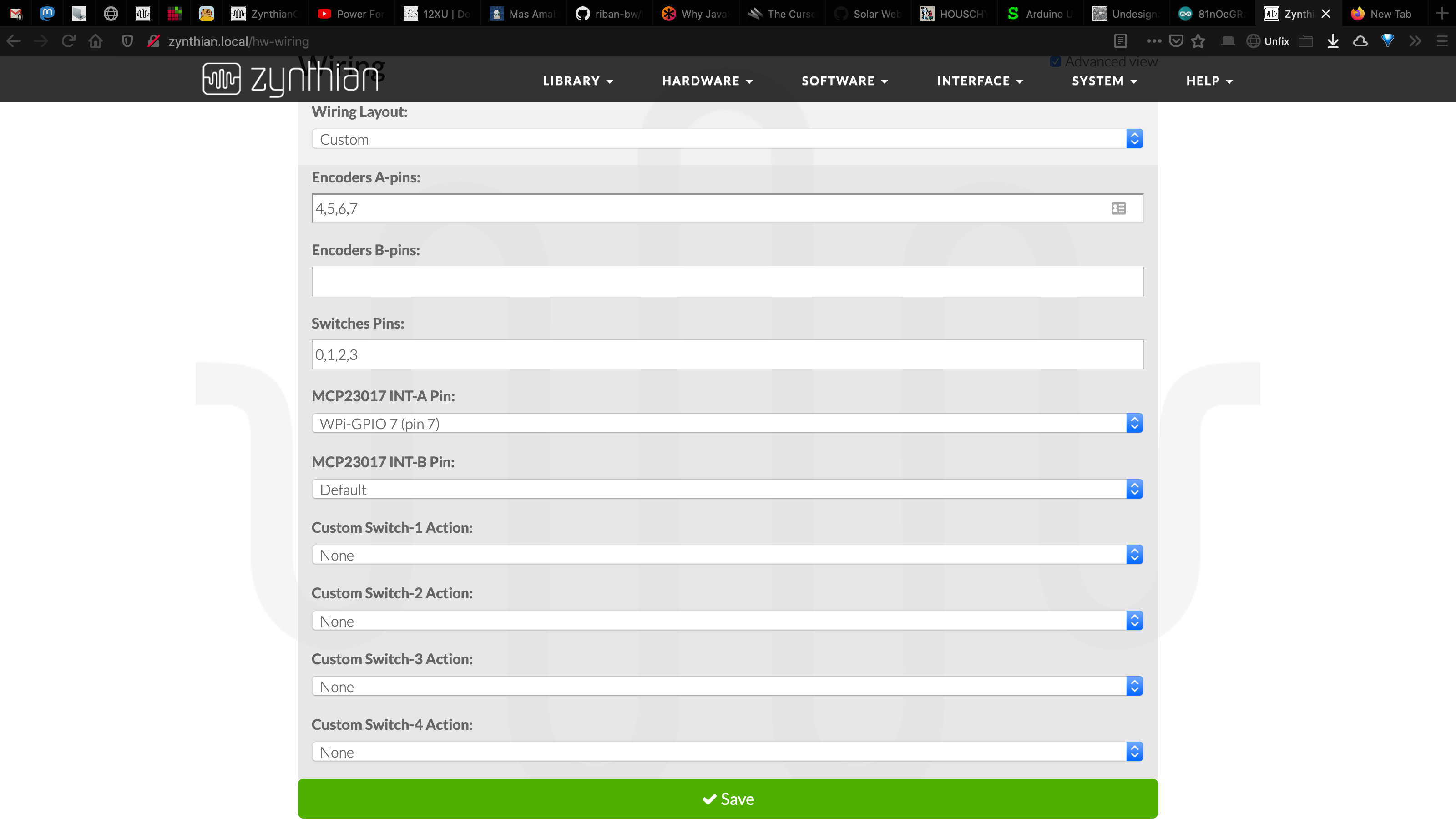
Any idea where to start looking for error?
Also, I’m having trouble when I use keyboard to navigate the UI, seems like something is always trying to scroll the list up, and I can’t use down button on my keyboard. I assume something is happening on the controller level.
Does keyboard behave this way when you have disconnected the i2c device? If not then it points to the i2c device almost working in that it is being interpreted as valid (but wrong) commands.
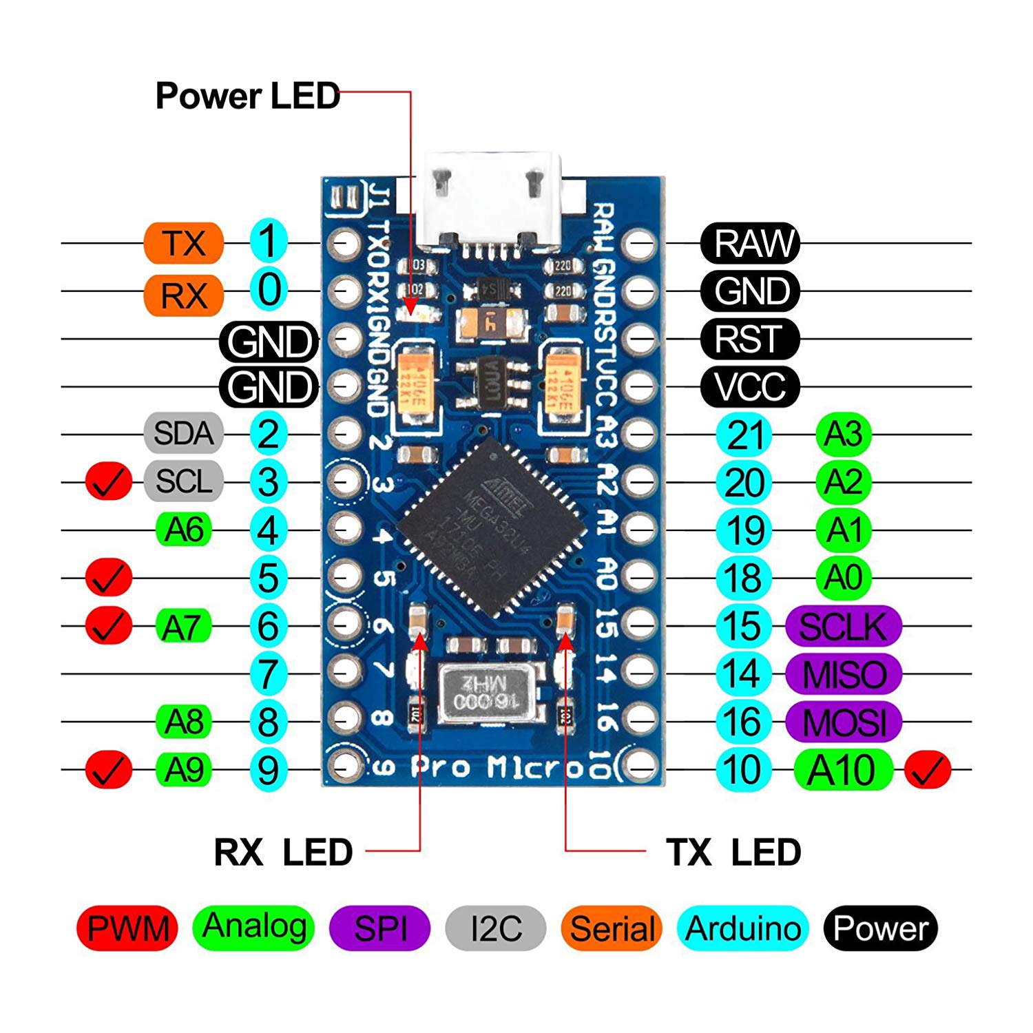
I can’t see pin 21 on a Pro Micro pin out diagram.
You are using the serial port pints (0, 1) so should force the serial port off with Serial.end().
There are no pull-up resistors shown and internal pull-up is not configured within your code. You need to pull pins up to ensure they don’t float and randomly trigger.
Initial debug could include:
- Stop Zynthian:
systemctl stop zynthian -
i2cdetect -y 1- This should show a table of connected I2C devices. There should be just one on address 0x08.
-
i2cget -y 1 8 0 b- This should get a byte containing the content of register 0 from the Arduino. This should be the index of a sensor with data or zero if no changes have occurred.
-
i2cget -y 1 8 x w(replace ‘x’ with the value retrieved in previous step)- This should get the value of the sensor as a 16-bit word representing a signed integer. For switches this should be 0 / 1. For encoders it should be +/- quantity of indents rotated since last read (or reset).
-
i2cset -y 1 8 0 0will reset the Arduino’s table, clearing all values back to zero.
If that doesn’t help then I would suggest removing encoder 1 and connecting a serial port then adding some Serial.print() debug commands to your code.
1 Like
Seems like it doesn’t depend on whether it’s connected or not, it works like this whenever any non-dummy wiring is selected in webconf…
It should be A3… Now I’m confused. Should I call it as 21 or A3 to use it as digital output? Or should I avoid using it as output at all?
i2cdetect -y 1 shows table with 08 in it, but i2cget -y 1 8 0 b always returns 0x00 and i2cget -y 1 8 x w gives 0xff00, no matter what I put instead of x.
Does it mean that the problem is in the code, or wiring?
Also about pulling pins up, is setting them to INPUT_PULLUP enough, or should I also add resistor? If so, what value should I use?