Strange about the keyboard interference. Let’s not worry about that just yet…
Use the digital pin names, not analogue names. I am worried that pin 21 may not work in some configurations. I can’t find a reference for it. You may need to use it as an input or output and it may or may not support pull-up. Find a datasheet for the device.
The fact that i2cdetect shows your device is a good start. The I2C interface is working. Also that you get results from i2cget which means your connection to RPi and the corresponding interface code is okay. (This does not prove anything about the interrupt but again, let’s look at that later. It could be the cause of your other scrolling issue.)
Internal pull-up should be fine. That is what I am using. I haven’t looked at your code in detail.
@sleepy
In the webconf I believe you should be specifying “100” level GPIO pins to get the RPi Code to look to the expander for additional GPIO rather than the built in pins on the Broadcom chip itself. @riban can you confirm?
Also remember that many Arduino devices run at 5V but the Raspberry Pi requires 3.3V interface so there may be risk of damage to the RPi if this is not considered. This article suggests the Pro Mini runs at 3.3V so should be okay. (I wish I had remembered this last night before connecting my nano directly to my RPi… .) I was hoping to test your code but I may instead have frapped my Pi. (Lesson learned: Don’t piss about with electronics late at night after a whiskey when you have a cold.)
You have changed the code for onI2Crequest & onI2Crecieve. These should be reverted to my code.
Inputs may be inverted (I think for some reason I used pull-down with active high but you are using pull-up with active low.)
You need to ensure the switches and encoders are addressed at I2C register offsets:
Switches: 64
Encoders: 114
I did this by creating all 64 Pot, all 50 Switch and all 50 Encoder objects but there is less memory in the Arduino to waste so you just need to map the I2C calls to get data from the relevant controller objects.
It may be worth testing I2C by not putting the switch / encoder code in and just returning static values. Get the I2C bit working then you can get the switch bit working (which should be fairly easy but allows you to figure out the offset mapping) then get the more tricky encoder stuff working.
Oops. I have 5v pro micro, not 3,3v pro mini… I got confused by this youtube video saying it was allright to hook it up this way for I2C with raspberry as a master device but not the other way around…
Thanks for the code review. I will try it out later today, hope it will work and I didn’t fry my rpi.
I had not broken my Pi - I was running a crippled version of Raspbian which did not support i2c. I have now tested it and it does work connected to the RPi. Your code has removed too much of my code - I started to fix it but got bored…
That should explain why it didn’t work for me I guess I need to learn to code beyond most basic stuff. Anyway, thank you, I would abandon this idea if it was not for your help.
I’ll work on the code a little more this evening.
I spent some time breaking my STM32 version then fixing it again. It seems that the flush is no longer required and actually breaks it. The point about offsets is… I lazily create 64 ADC controller objects then 50 switch controller objects then 30 encoder controller objects and stick them all in an array. I then access the array element (controller object) indexed by the incoming I2C register index. This probably won’t work on the Arduino because it gets close to using all the available memory. You are creating just 4 switch objects and 4 encoder objects but if you index the array using the I2C index then you will overshoot the array because those will start at 65 / 115 respectively. I am tempted to roll up my sleeves and update my code to accommodate other processors. I can see that an Arduino or other device may be handy to use for fewer controls.
My debugging slowly progresses, and I guess I start to understand this code a little more
Quick question, in your snippet you posted you have this data array in sendValue. What exactly should go to this array? controller index and value?
The Zynthian will request a 16-bit signed integer which is transmitted over I2C as 2 byte 2’s compliment word. For switches this is simply zero one. For encoders it is a positive or negative value representing the quantity or notches turned, positive in clockwise direction and negative in anticlockwise direction. So the value of the encoder detection gets encoded by this code. The resulting 16 bit word gets sent via I2C as 2 bytes. I am not at my computer but iirc the I2C library writes the buffer (data[]) by passing a pointer to the buffer and the quantity of elements (2).
Data[] contains the value. The register index was already requested by Zynthian to trigger this response.
I almost got it to work in commandline. i2cget -y 1 8 x w returns changes for selected address, the only problem is i2cget -y 1 8 0 b always returns 0x41, which is my SWITCH_START+1. Didn’t have a chance to track it down yet
For some reason my switches were returning 0 when pressed and 1 when released, that’s why I had this problem. Now i2cget -y 1 8 0 b returns the lowest index of the changed controller, is that how it supposed to work? With this done what are the next steps to make it work with UI?
You have pull-up on the inputs and are taking it low when pressed hence you will get 0 when pressed. You just need to invert this in the readSwitches code, e.g.
int nValue = !digitalRead(...
The code I wrote would return the next encoder / switch that had changed. That would initially be the lowest but would move to the next as you read each one. The point being that if there was a flapping input it would not block the reading of others. So if you adjust encoders 115 and 116, the interrupt signal should assert. Reading register 0 should return 115. Reading register 115 should return the value you adjusted the encoder, e.g. 2 if you turned it 2 notches clockwise. The interrupt pin should still be asserted. reading register 0 should now return 116. Reading register 116 should return the value of that encoder. Reading 0 should now return 0 as there are no more switches or encoders that have changed value. Reading register 115 and 116 should also now return 0 because they should get reset on read. Encoders give the delta since last read, i.e. the distance the were moved since last read. Anticlockwise rotation should decrease the value and negative numbers look like large numbers, i.e. -1=0xFFFF, -2=0xFFFE, etc.
Switches work similarly but only provide values 0 for released and 1 for pressed. Pressing or releasing a button should trigger the interrupt and populate register 0 and reading a switch should clear the interrupt and register 0 (if no other inputs need to be read). Reading a switch register will give its current value.
Check the above behaviour is correct and that your switches are at registers: 65,66,67,68 (0x41…0x44) and your encoders are at registers: 115,116,117,118 (0x73…0x76).
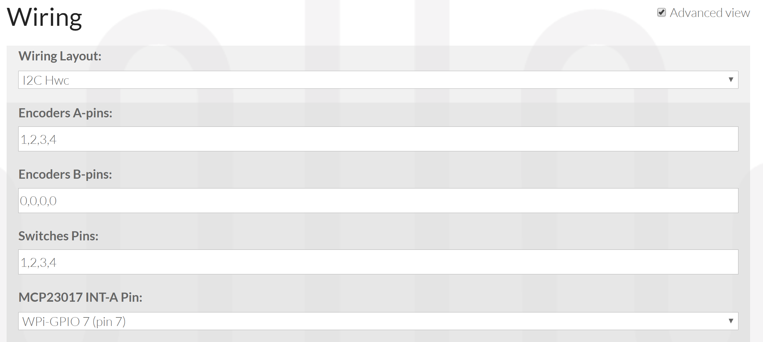
Once this is done you should be able to connect the I2C bus and the interrupt to Zynthian and select I1C Hwc Wiring Layout (see my previous screenshot in this topic above). Set the Encoder A-pins and Switch Pins to 1,2,3,4 and the MCP23017 INT-A Pin to WPi-GPIO 7 (pin 7) (or whatever pin you connect to) and voila - hopefully it bursts into life. Bear in mind the position of the encoders, 1=top left, 2=bottom left, 3=top right, 4=bottom right. (I laid them out left to right so have to adjust my webconf accordingly.)
i2cget -y 1 8 0 b returns lowest changed register +1 (I described it wrong in previous post)
i2cget -y 1 8 x w returns correct values both for switches and for encoders, as you described
registers are set correctly
webconf is set as in your screenshot
what am I missing? I was thinking 5v messed up the interrupt pin, I divided voltage with the resistors (btw, is it a bad idea?) for the interrupt and tried another pin, and it still doesn’t work.
Few times I got reactions of the UI, but I could not recreate it
I rewrote it to create only 8 controllers (really roughly with a lot of hardcoded stuff at the moment) and it didn’t help. I still get all the correct values from the command line, but it doesn’t work with the UI i2cencoders.ino (8.1 KB)
If that was a problem, why I was able to get values through command line? I thought it wouldn’t work at all if the memory was full.
Do I understand correctly that interrupt should be high unless there’s some change in the controller, then it should get low for a moment, telling the master that it should send the request, and then again become high?
I’ve checked the voltage on mine, and for some reason it does not get back to high after the change…
 .) I was hoping to test your code but I may instead have frapped my Pi. (Lesson learned: Don’t piss about with electronics late at night after a whiskey when you have a cold.)
 I guess I need to learn to code beyond most basic stuff. Anyway, thank you, I would abandon this idea if it was not for your help.