Arduino USB HID Controller

I need to organise some sensible mapping for all mine. I need a couple of weeks off work to concentrate on it. I plan for weekends but they tend to get misdirected.

I have seven of the things ( could be wrong on that…) one of which controls a behringer 1820 mixer… Not sure I’d dare to take it on stage yet. Not there are any stages to go on at the moment.

1 Like

The prototype is working!
Progress and photos from this week.


STM32 based USB-C connected Select Encoder connected as Keyboard. Next step will be to find hopefully 15 more GPIO pins conveniently placed to make wiring 1:1

@riban
Keyboard encoder rotation action does not match Internal encoder rotation action. For example: The Select keypress encoder rotation generates Uparrow/Downarrow which operates UI up/down Synth Page Menu. This action should operate the Lower Right Corner Midi Knob on current page, same as the MCP23017 built-in wired encoder. The other keypress encoders I think have the same issue.

zyncoder: master (d706b12)
zynthian-ui: master (2ea9647)
zynthian-sys: master (a06533e)
zynthian-data: master (74ceb35)
zynthian-webconf: master (d25055c)

I’ll probably finish out the hardware build before I try to go after the software.

2 Likes

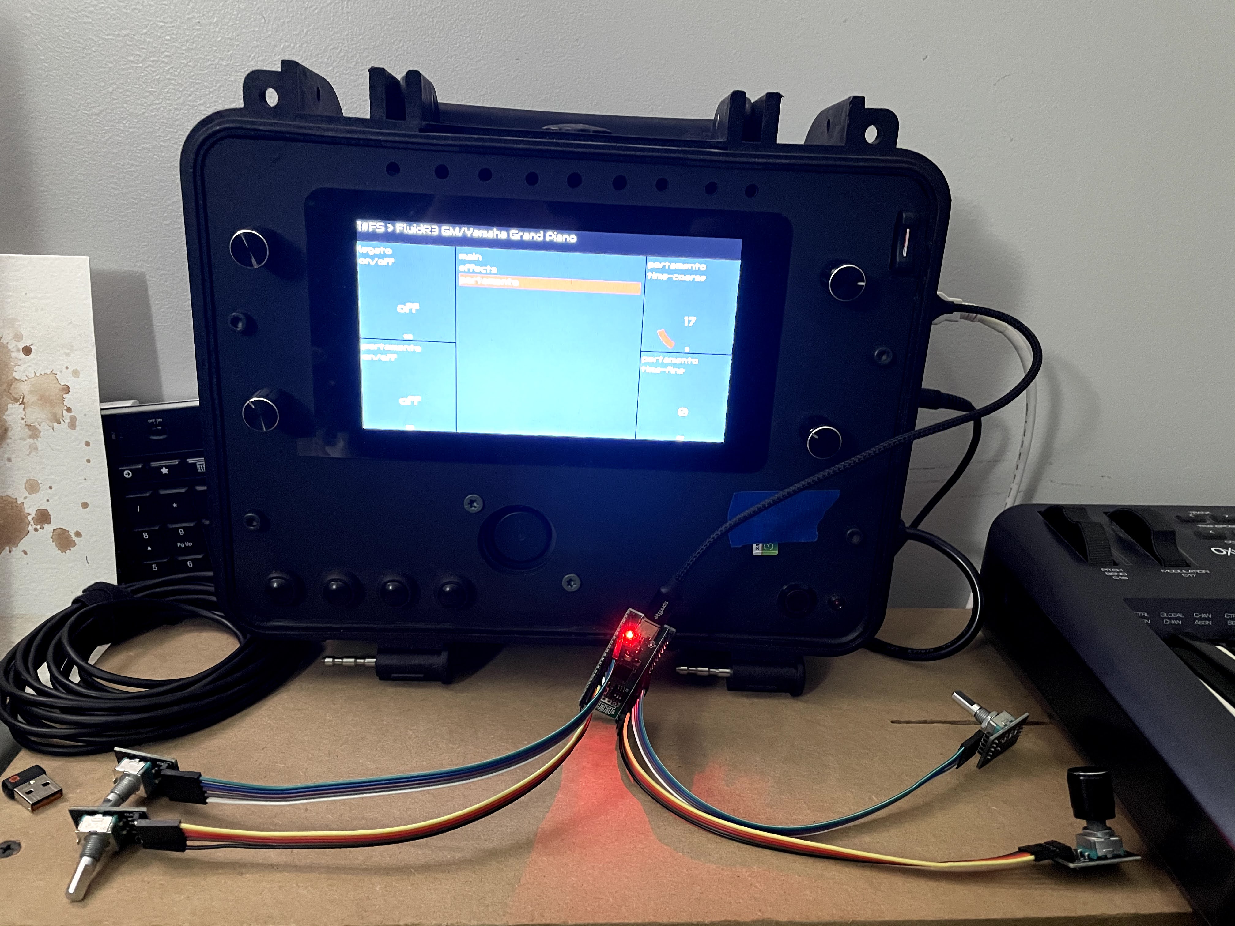
The prototype is almost working.


Now quite what we mean by working, is a debate that I’m sure I could run to hours but best to save you such concerns and leave it to the brave boys and girls down in the R&D department and there many, many hours spent on the zynthian tower dungeons, “encouragement equipment” to answer this question.

A thingy has been built and it’s almost ready to have a name so suggestions along the lines of zynrduino or zynhui would be considered.

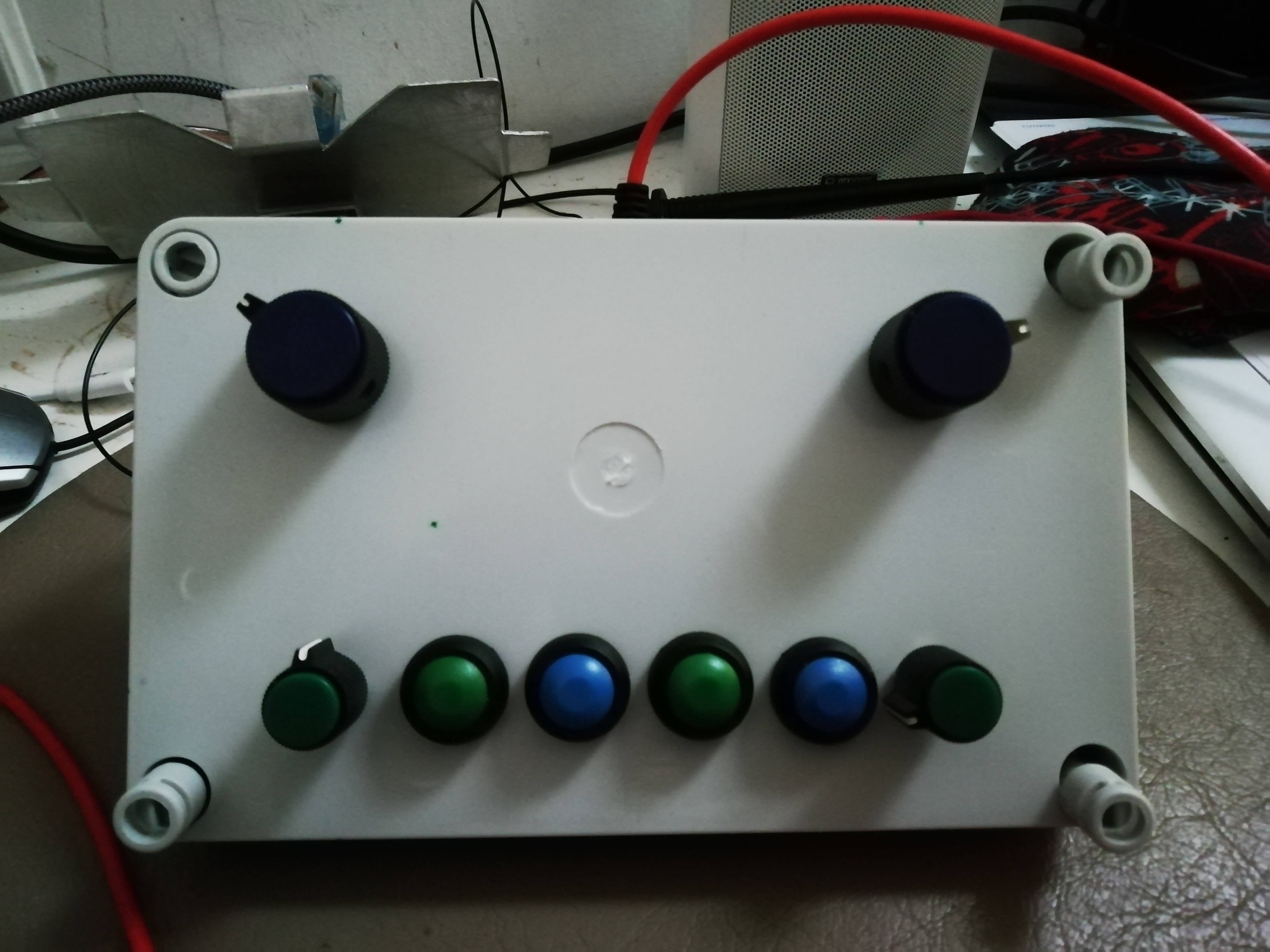
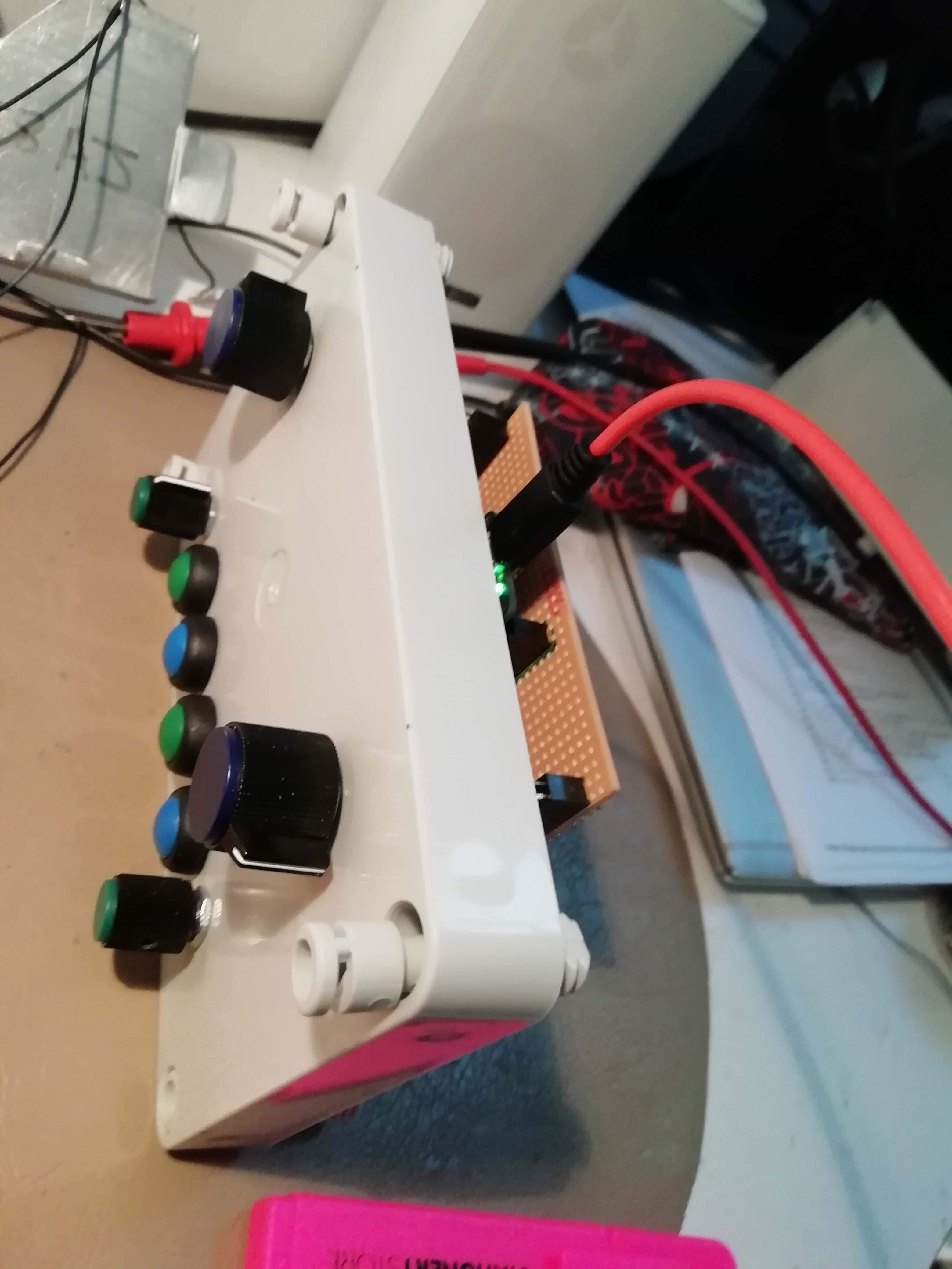
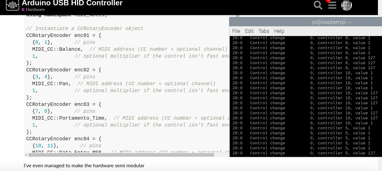
I’ve even managed to make the hardware semi modular

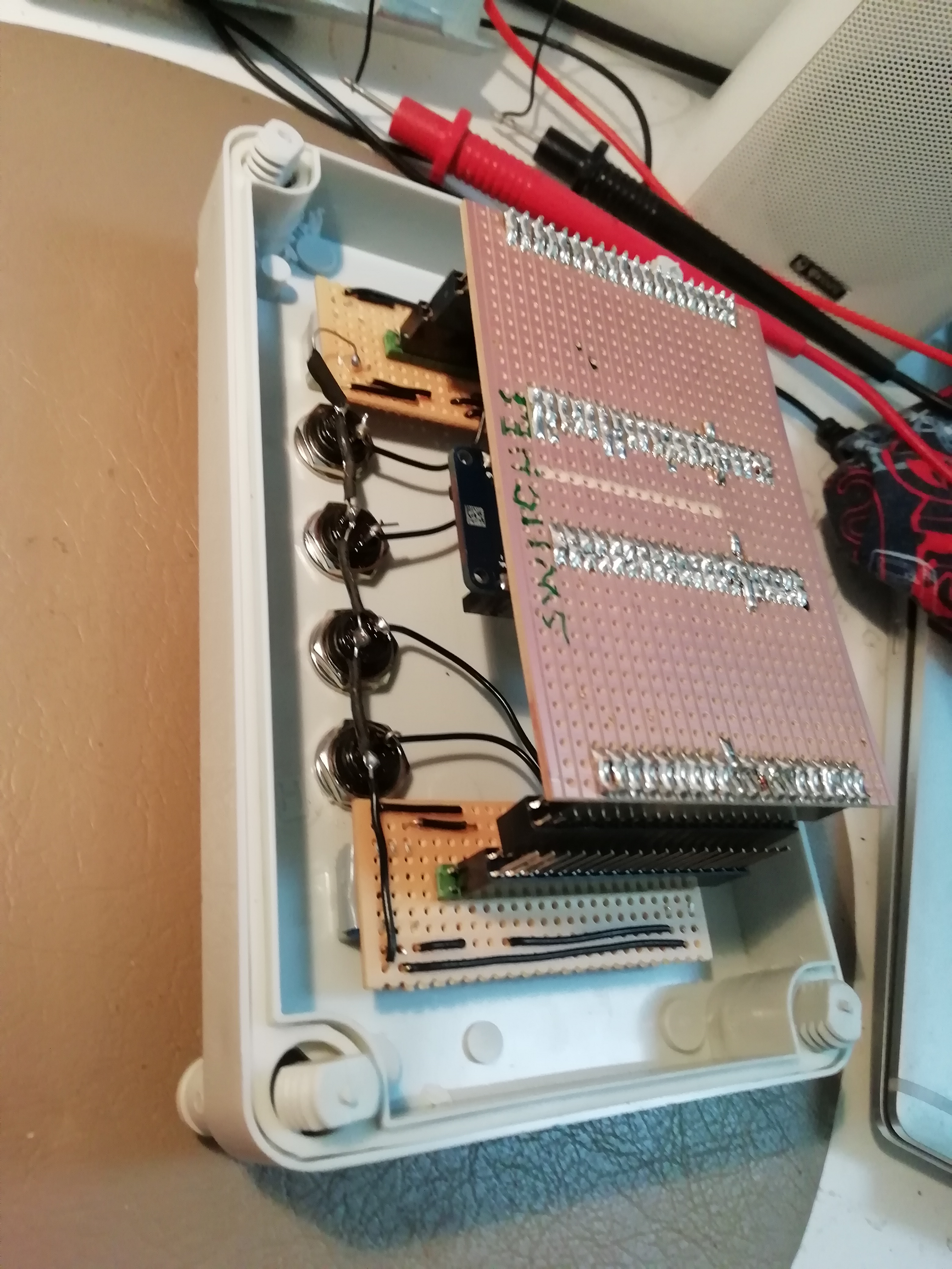
3 of the encoders work, which is odd cos I’m pretty sure they worked as a switch on the Pedal board, and I’m fairly sure the signal makes it to the pins.

Which looks great until you realise that the Channel Encoder on pins 10 & 11 just doesn’t function.

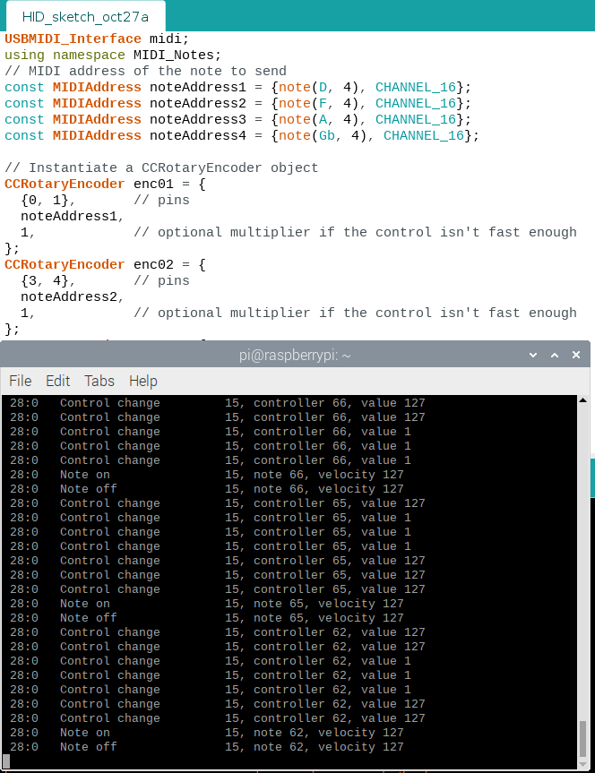
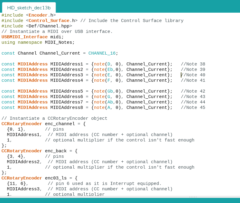
Since it’s a big exercise in cut & paste I can’t find the construction of the MIDI_CC object that allows me to set the MIDI out channel.
So I’d love to know how to do that . . .

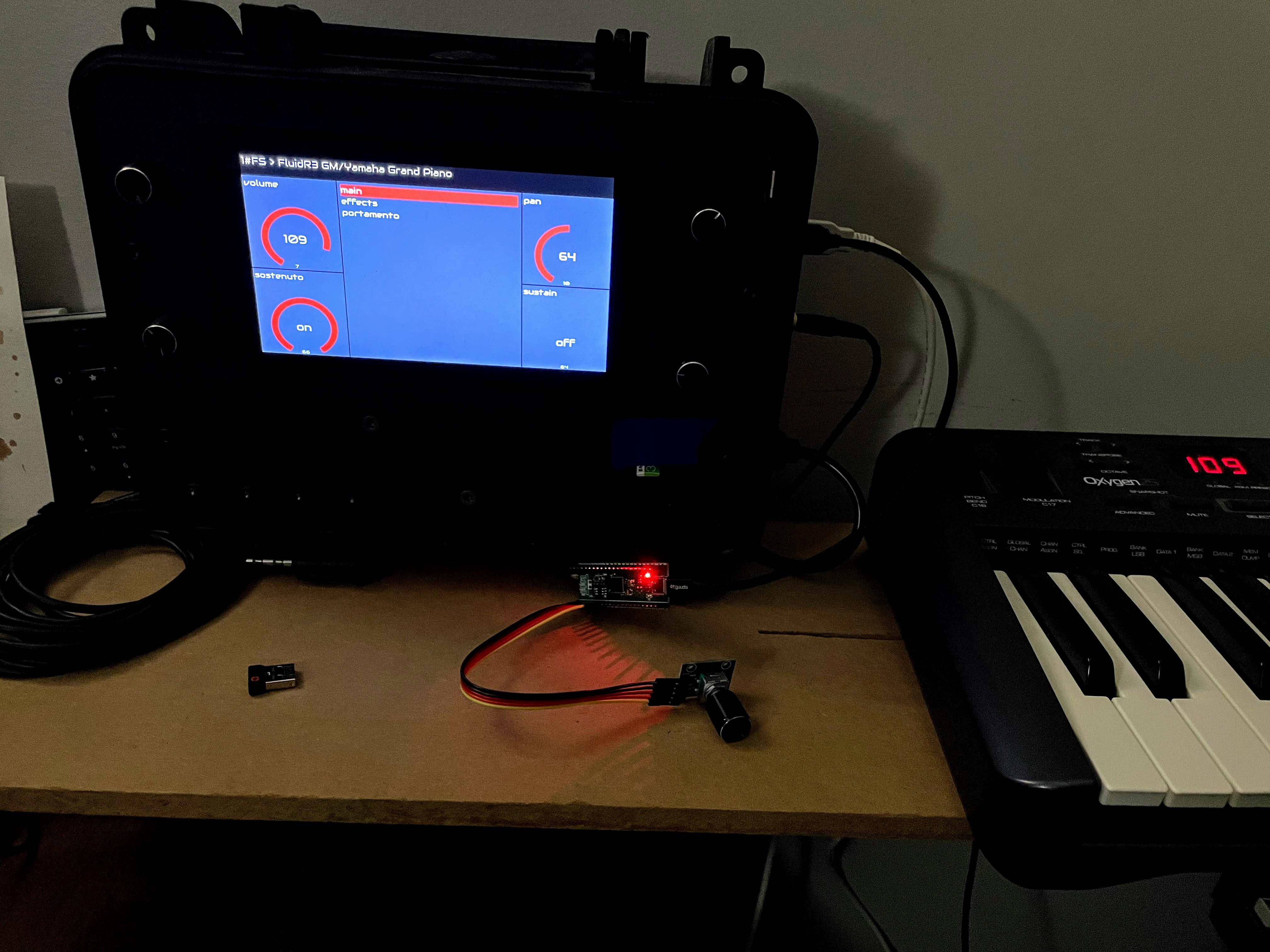
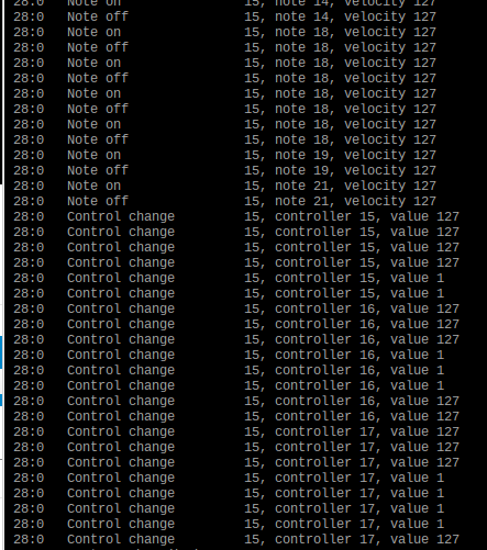
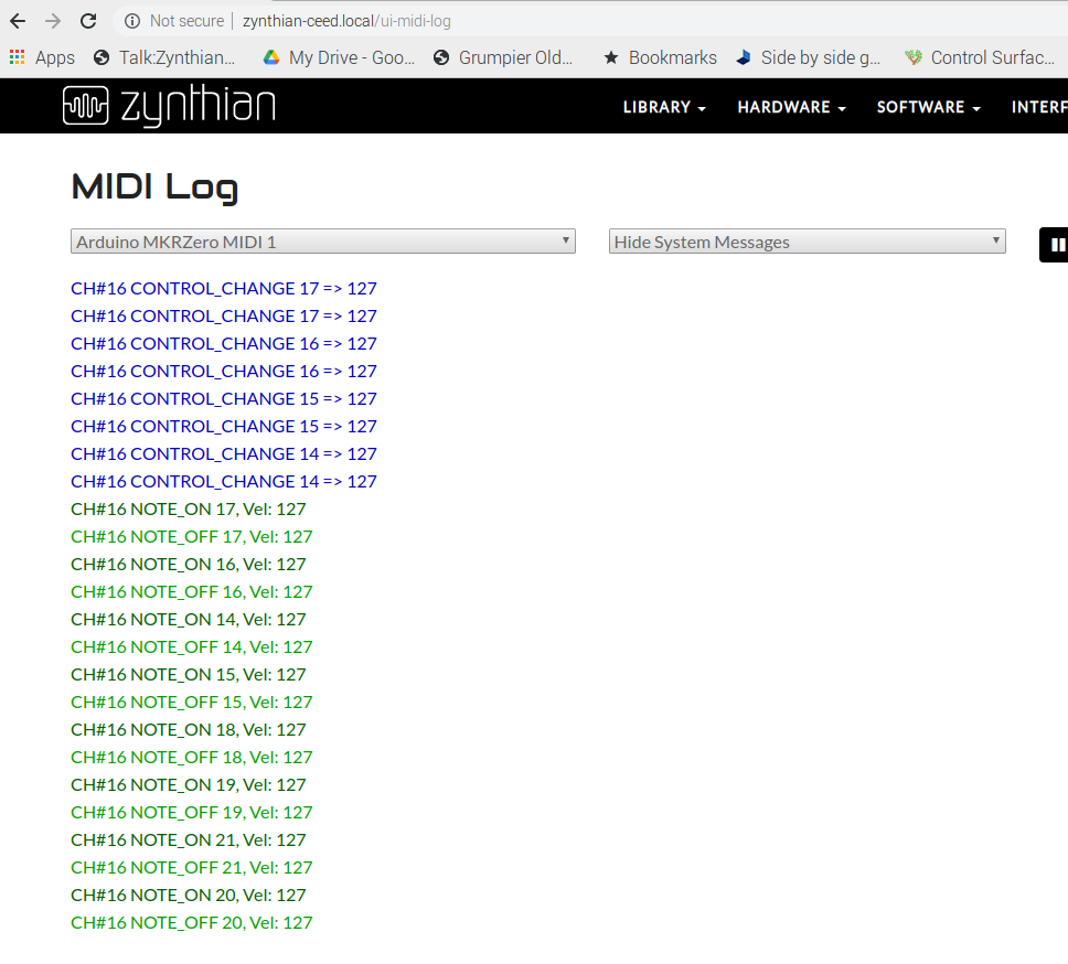
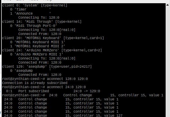
Otherwise with these setting the encoders sent value 1 or 127 depending on which way they are going, and continue to do so for ever. So they make good signals to control a zynth.

Have wired up the basic encoder switches and need to add code for front panel switches.

Might add a LED or two for some feedback, and testing.

#include <Encoder.h>
#include <Control_Surface.h> // Include the Control Surface library
// Instantiate a MIDI over USB interface.
USBMIDI_Interface midi;
using namespace MIDI_Notes;

// Instantiate a CCRotaryEncoder object
CCRotaryEncoder enc01 = {
  {0, 1},       // pins
  MIDI_CC::Balance,  // MIDI address (CC number + optional channel)
  1,            // optional multiplier if the control isn't fast enough
};
CCRotaryEncoder enc02 = {
  {3, 4},       // pins
  MIDI_CC::Pan,  // MIDI address (CC number + optional channel)
  1,            // optional multiplier if the control isn't fast enough
};
CCRotaryEncoder enc03 = {
  {7, 8},       // pins
  MIDI_CC::Portamento_Time,  // MIDI address (CC number + optional channel)
  1,            // optional multiplier if the control isn't fast enough
};
CCRotaryEncoder enc04 = {
  {10, 11},       // pins
  MIDI_CC::Data_Entry_MSB,  // MIDI address (CC number + optional channel)
  1,            // optional multiplier if the control isn't fast enough
};

NoteButton button03 = {
  2,                       // Push button on pin 3
  {note(D, 4), CHANNEL_16}, // Note C4 on MIDI channel 16
};
NoteButton button06 = {
  5,                       // Push button on pin 5
  {note(F, 4), CHANNEL_16}, // Note C4 on MIDI channel 16
};
NoteButton button07 = {
  6,                       // Push button on pin 6
  {note(Gb, 4),CHANNEL_16}, // Note C4 on MIDI channel 16
};
NoteButton button10 = {
  9,                       // Push button on pin 1
  {note(A, 4), CHANNEL_16}, // Note C4 on MIDI channel 16
};


void setup() {

  Control_Surface.begin(); // Initialize Control Surface
}
void loop() {
  Control_Surface.loop(); // Update the Control Surface
}
1 Like

Ol this is getting silly. I can replace the failed encoder

NoteButton testbutton1 = {
10, // Push button on pin 6
{note(Eb, 5),CHANNEL_14}, // Note C4 on MIDI channel 16
};
NoteButton testbutton2 = {
11, // Push button on pin 1
{note(Bb, 5), CHANNEL_14}, // Note C4 on MIDI channel 16
};

And that works … How does THAT happen…?

Anyway doesn’t interrupt the overall process the front panel switches now all work as well.

1 Like

@wyleu, For some reason that controller layout reminds me of an Angry Robot
“o_o”

I do like the MIDI options you have, it has me dreaming now of a hybrid controller that does both? IDK. Perhaps I should be looking at MIDI all the way.

2 Likes

4x encoders all work with default mapping:


Base functionality is done.

On to the push buttons.

Which encoder library are you using?

I’m very confused by my 10/11 encoder. It works as a source of MIDI keysdown and keyup but won’t run as an encoder even thou’ the other three all do.

@smiths73v3 Do you have enough spare I/O pins on the arduino to do 4 local keys to complete the external interface?

@riban have we still got that test framework software available?

We are fairly close to a manual testing schedule here…

Zynth Name Control Movement Qwerty MIDI Comment
Channel Encoder 1 Turn Left - - -
Channel Encoder 1 Turn Right - - -
Channel Encoder 1 Released ->Pressed - - -
Channel Encoder 1 Pressed -> Release - - -
Back Encoder 2 Turn Left - - -
Back Encoder 2 Turn Right - - -
Back Encoder 2 Released ->Pressed - - -
Back Encoder 2 Pressed -> Release - - -
L/S Encoder 3 Turn Left - - -
L/S Encoder 3 Turn Right - - -
L/S Encoder 3 Released ->Pressed - - -
L/S Encoder 3 Pressed -> Release - - -
Select Encoder 4 Turn Left - - -
Select Encoder 4 Turn Right - - -
Select Encoder 4 Released ->Pressed - - -
Select Encoder 4 Pressed -> Release - - -
Switch 1 Switch 1 Pressed -> Release - - -
Switch 1 Switch 1 Released -> Press - - -
Switch 2 Switch 2 Pressed -> Release - - -
Switch 2 Switch 2 Released -> Press - - -
Switch 3 Switch 3 Pressed -> Release - - -
Switch 3 Switch 3 Released -> Press - - -
Switch 4 Switch 4 Pressed -> Release - - -
Switch 4 Switch 4 Released -> Press - - -

We do have the TestCollab project but I haven’t looked at it much. I can’t remember the licencing for this which may have changed as they have developed their business model. I still think it a good idea but my experience tells me that this requires significant effort to maintain which I find challenging to provide… I would rather be building it than testing it!

@wyleu,

I’m using “Simple Rotary 1.1.2 Library from mprograms”
I am mostly happy with it (it works!) but it’s a little slow. I’ll probably tune some of the advanced parameters for those encoders once I have the whole thing working.

I am using a clone of the “BlackPill” as my platform. I have plenty of spare GPIO pins at this point for wiring in the buttons. Just need to figure out the easiest layout.

So for your issue on 10/11… The thing to look at is Interrupts…

  • External Interrupts: 8 (0, 1, 4, 5, 6, 7, 8, A1 -or 16-, A2 - or 17)

Can you post a table of each Pin and what they are wired up to?
Looking back at what you already posted, I would swap note buttons to 10/11 and move the encoder to 5/6.

I would bet you a :face_with_monocle: that the encoders need interrupts, and the Note buttons do not. :slight_smile:

By careful swapping ( the modular approach helped here ) I’ve narrowed it down to the mkrzero. ( the encoder that fails is always connected to pins 10/11. So that at least means my soldering is ok. I might try with a couple of debounce caps 10n or /and some 2.2K pull up resistors to see if that improves things.

Sound feasible…

The library I’m using claims to deal with all the bits and pieces for you, and I’ve not had any interrupts to configure.

As I say 3 of the encoders work lke a dream but any encoder connected to 10/11 fails althou’ it will respond as switches… Software eh…?

update…

I expect I will be getting my :face_with_monocle: ready . . . From the manual.

Presumably as long as one of the pins has an Interrupt on it it should respond suitably if, perhaps, a little sluggish…

I’ll swap D6 & D10

Well if we do this with MIDI control we can automate the operating side of it as a mock.

Indeed that is the fix… !!! Extra portion of rook soup for @smiths73v3 !!

…and I suppose I’ll have to get a :face_with_monocle: together…

For Tim Smith… R.I.P

1 Like

Awesome!

Right my next problem is my lack of understand C…

I wish this all to happen on MIDI Channel 16 ( 15)

And that’s the way to do it…

So I’ve got it selecting a master channel . . …

Which makes things a little more configurable. And I’ve refined the interface to Putting the same MIDI note as a push switch onto the same CC so there is some sort of consistency.

and it sends out MIDI . . .

So connecting it to a Zynth . . .

it appears . .

It makes it to aconnect -l

image

it makes it to the Arduino MIDI display . . .

But sadly NOT to zynmidirouter…

If it picks up the Behringer Why not the Arduino…?
:smiley:

Are you sure that the MIDI channel you are using will control what you expect?

I’m after Encoder & button control over MIDI Channel 16 …
I realise there’s some code in zynthian_gui.py to write.

This is the remote box for the pedal zynth.

Not sure whats happening on the zynth with the arduino MIDI connection…

Anyone make any sense of this …?

image

It rather depends what you are doing. It looks like you have listed your MIDI devices including the Arduino, connected that to a running instance of aseqdump and then adjusted some values which show in the output window.

Do I win a prize?

It more the patching to port 128 which I didn’t do. It still doesn’t turn up as a zynthrouter object in midi log