Arduino USB HID Controller

The improved UI Key bindings have added up/down on the 4 standard Encoders as well as assignments for every switch press, short, bold and long.

I’m dreaming of an outboard USB HID keyboard with Arduino Leonardo connected to 4 encoders and converting those to the corresponding keypress actions. Anyone have a work in progress, or suggestions before I order a few and start messing around with this?

My minimalist stage config is now looking like a Pi4 with USB sound card, and then in the studio I’ll hook up HDMI, and an Encoder Keyboard block for twisting knobs and assigning MIDI’s.

1 Like

Some of this work is done here and adapted/ simplified here. This is an I2C interface but the encoder and button code could be used. There are some HID libraries for Arduino. I am using STM32 hardware and the Roger Clarke libraries which I started to detail here. The idea of a USB keypad was discussed here..

I quite like the idea of a USB control pad but there is benefit from having the knobs close to the relevant part of the screen. Of course that loses some benefit when the screen is 55" and the knob is 20mm. (I couldn’t fit another measurement scheme in that sentence :wink:. )

3 Likes

Thanks @riban!
I remember reading some of this along the way. I was tempted by the USB keyboard, but was limited at the time by issues with the Pi3, which I’ve now replaced. That and the switch press was not yet fully implemented.

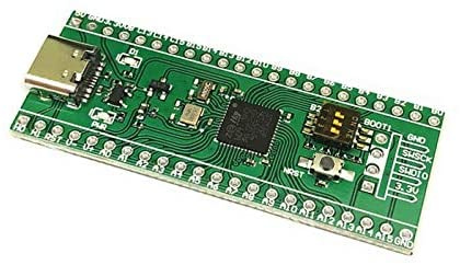
I’ve ordered up USB-C plugable Arduino Pro-mini which should arrive tomorrow, the USB-C STM boards should arrive Tuesday.

At this point, I’m leaning towards the STM32 thanks for the tip on that. I think I can connect 5pin arduino style encoders directly with encoder 5v/gnd supplied as GPIO which would make this a straight wire for a nice clean build. I suppose I should also think about implementing S1-S4 since that’s becoming the standard.

Without adding any multiplexing circuitry you need sufficient GPI pins for each switch:

  • 2 GPI per rotary encoder: 8
  • 1 GPI per encoder push button: 4
  • 1 GPI per switch: 4

So that is 16 available GPI which can be challenging on some microcontroller boards. The STM32 development board should be fine. You also need to daisy chain or star wire a ground to each switch, including the centre pin on the encoders. It is unlikely there will be sufficient ground (0V) pins on the MCU board for one-to-one wiring.

If you are using encoders with onboard pull-up resistors then you need to either remove the resistor or wire VCC (3.3V or 5V, depending on the MCU) to the encoder’s VCC / +V pin. This is frustrating because the extra component on the encoder boards needlessly adds to the complexity. (I use raw encoders and build my own board.)

The Arduino Pro Mini is based on the ATmega328 which does not have USB port. The development board may have USB serial interface implemented by an extra chip but this will always be a serial port, not HID USB. The STM32 has built-in USB which can be configured as HID so you may find this the better option. There are other boards that support HID USB but you have purchased those so it looks like the STM32 will be your choice. Feel free to hit me up for help with this. I can share my experience and hopefully ease the development.

1 Like

@riban, Thanks!
Yes, I think we are coming at this from a similar background. I appreciate the advice, and experience.

I misspoke, it’s the arduino pro-micro (ATmega32U4), and I picked for HID or Rubber Ducky support :wink: I probably won’t implement on this MCU since the STM seems to get me closer to what I actually want.

Looking at the STM controller, I am assuming there is some way to turn any of the PA_x,PB_x or PBC_x pins brought out to the edge connector as GPIO. I was then going to divide them into blocks of 5, one output 0V, one output 3v/5v, and the three remaining as GIOP input for A,B,SW If this scheme will not work, I’m going to have to use one of your suggestions.

I’ve done the resistor depop on those encoders before, but I didn’t like doing that. I’m going for off the shelf encoders. That may prove to be too ambitious.

Ah yes the pro micro has onboard USB but only 12 digital I/O pins. Most of the digital I/O pins on the STM32 can be used for digital input. Two are used for USB but it sounds like those are the only ones you need to worry about. I’m not sure if using digital I/O pins as supply pins is a good idea. It will work up to a point but you may find you saturate the current limits which could give some weird results and possible damage the chip. There was a topic on this forum recently about wiring supply feeds. If you don’t mind picking up a soldering iron then you can very easily create a distribution strip of pins by soldering a header strip to a bit of Veroboard.

The first step was to figure out how to get code onto my BlackPill Clone.
image

I was able to program the STM32 using the Arduino IDE using the built-in DFU bootloader. Here’s a video that walks through the steps required to setup the IDE.

Now the real fun starts…

The current default keymap is defined with these encoder bindings:

  • Back Down - “down” “Caps Lock”
  • Back Up - “up” “Caps Lock”
  • Back Short - “esc”
  • Back Bold - “esc” “Shift”
  • Back Long - “esc” “Ctrl”

  • Select Down - “down”
  • Select Up - “up”
  • Select Short - “ret”
  • Select Bold - “ret” “Shift”
  • Select Long - “ret” “Ctrl”

  • Layer Down - “down” “Shift”
  • Layer Up - “up” “Shift”
  • Layer Short - “l”
  • Layer Bold - “l” “Shift”
  • Layer Long - “l” “Ctrl”

  • Snap Down - “down” “Ctrl”
  • Snap Up - “up” “Ctrl”
  • Snap Short - “s”
  • Snap Bold - “s” “Shift”
  • Snap Long - “s” “Ctrl”

The Switches I propose to be mapped as:

  • S1 - “b”
  • S2 - “b” “Shift”
  • S3 - “b” “Ctrl”
  • S4 - “b” “Caps Lock”

Trixy design decision. We can map S1-S4 buttons to CUIA functions. We have a default mapping of HID keys to CUIA functions. It feels wrong to map HID events to S1-S4 button events. It would be more logical to map the HID events that your remote buttons create (e.g. ‘b’) to the same CUIA events that you map the S1-S4 buttons to, i.e. ‘b’ is not S1, it is mapped to same CUIA as S1.

1 Like

FOLLOWING TWO POSTS MOVED FROM SEPARATE THREAD STARTED AT THE SAME TIME

Regrettably, I have to accept that @riban 's lucky guess about the quality of long 12c connections was, for once, actually accurate. This means that I am abandoning that particular route to allow wire linked remote control of the pedal board zynthian.

But do not dispair good toilers at the zynthian mines! Liberation may still be attained! Another ludicrous hair brained scheme has occurred to me…

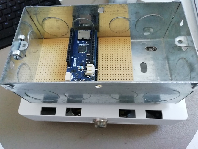
Using an arduino mkrzero ( the wyleu adopted lump of choice at the moment) to bridge between the All-in-one 12c connection and a couple of interupt pins and a USB connection which could feed instruction into the USB port of a zynthian.

This seems a rather more supportable mechanism, and also relieves the world of soldering up tiny aircraft connectors and all the associated brew haha.

But, and here I appeal to the slightest element of democracy we are allowed down her at the coal face. How best to implement it?

Suggestions
1/ Fake the keyboard QWERTY mechanism over USB to present all operations as key presses derived from the I2C behaviour of the encoders, encoder switches and i/o switches ( are the later supported in the QWERTY keyboard protocols…?)

2/ Fake the MIDI mechanism over the USB to present all operations as MIDI Messages derived from the 12C behaviour of the encoders, encoder switches and i/o switches

3/ Fake the OSC mechanism over the USB to present all operations as OSC Messages derived from the 12C behaviour of the encoders, encoder switches and i/o switches

4/ Ignore the i2c and work it all out from encoders and switches on the mkrzero i/o ports. transmitted in one of the mentioned formats over USB

5/ Send highly trained observant ravens to peck at the touchscreen in response to encoder … etc…

From a community prospect I suspect doing all of these might be beneficial with a suitable protocol switch althou’ ravens are a little thin on the ground, since they have been discovered to make very fine soup…

Any thoughts …? Minimum coding in the arduino and zynthian realm would, of course, be advantagous in so many ways.

I put it the court that the expert witness for the prosecution was in fact calling on several decades of experience when he proffered the hypothesis that I2C, being specifically designed for short distance, internal communication would be at best unreliable when exposed to the ravishes of the outside world. The honourable gentleman may be advised to take heed of his own ravenous existence and avoid tempting said avian menace from cable attack.

3 Likes

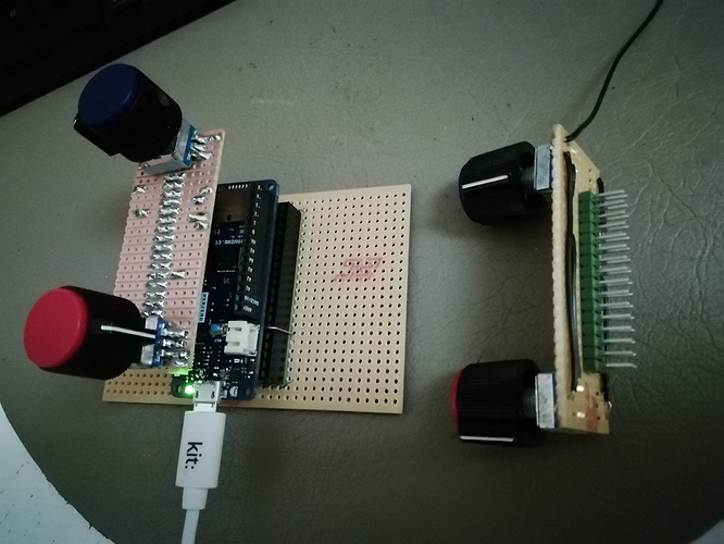
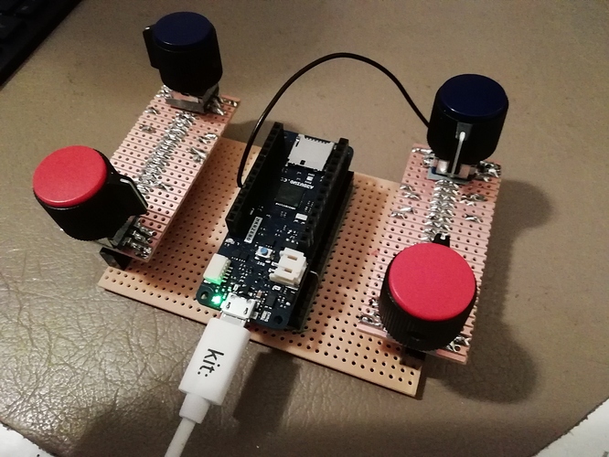
Rather a small change in tack from the wyleu implementation. I’ve built the traditional thingie, indeed two of them …

Arduino Pin Encode PCB 1
D0~ Channel Top
D1~ Channel Bottom
D2~ Channel Switch
D3~ Back Top
D4~ Back Bottom
D5~ Back Switch
Arduino Pin Encode PCB 2
D11~ L/S Top
D10~ L/S Bottom
D9~ L/S Switch
D8~ Select Top
D7~ Select Bottom
D6~ Select Switch

Which works very nicely with my existing pedal board code and renders up MIDI messages when moving encoders and switches. . . .

All cleverly contrived with a couple of bits of stripboard and a couple of edge connectors.

So this actually emits MIDI … which there is kind of a sketch for.

There’s a bit of confusion about the MIDI controller elements and it, perhaps, needs unifying…
For instance are we declaring MIDI or Qwerty as canonical?

Where do we decide what constitutes short, bold & long? Really this should be declared back at the CONTROLLED Zynthian especially as we can edit the lengths… so perhaps we should be sending MIDI Note(Encoder (1-4) ON on switch Down then MIDI Note(Encode(1-4) OFF as the switch is released. upon which ever MIDI control channel is selected on the CONTROLLED zynthian ( no way round this one without a back channel, unless we always default to MIDI channel 16 which would seem sensible)

We send MIDI Note(Encoder (1-4) ON up & OFF on each Click on the encoder going up and the appropriate note for each click on encoder going down.

So in addition to the existing MIDI implementation …

Should we add

Action Encoder MIDI Note
Pressed Select ~ (something that matches existing mappings )
Released Select
Up Select
Down Select

etc…

or have I forgotten some core GUI functionality…?

And with the addition of a couple of edge connectors we have the (pre Switch) encoder configuration . . .

3 Likes

So I went and tried the QWERTY thing, with an actual keyboard and many of the events described in the webconf are not working. Such as the encoder up/down for back,layer,snapshot as well as the switch presses for these… I may have to do some Zynth-side UI code before this is working.

@wyleu, we have slightly different use cases here yours is MIDI, which has it’s advantages for sure… Like being currently implemented :slight_smile:

Anyways, for a QWERTY implementation of the encoders, I was expecting that the SHORT, BOLD, LONG would be determined by the encoder board, and passed up to the Zynth as the appropriate keypress.

Somehow I’ve made zero progress on this since last week… Perhaps I can get the pin headers soldered tomorrow, and a mock up encoder wired in.

1 Like

I’m doing Midi first simply because it’s easy from the kit I’ve got. I intend todo qwerty after that and then osc… Hopefully we can unify all the approaches.

Please give an example of what does not work. I use QWERTY keyboard extensively for testing find development and haven’t noticed issues but I am not touching all parts of the functionality.

When I do any of the “Up/Down” operations I do not see the encoder value onscreen for each UI element move up/down as expected. [ctrl]-[up], [shift]-[up],[caps lock]-[up]

Normal up/down does work, but it changes the selected “Synth Parameter Page” same as [ret] would do. I expect this to do the UI parameter for the Select box.

Basically, I want up/down operations to be mapped identically to the same as the physical encoder up/down.

Yes, we want a completely defined set of operations.
GUI interaction is weak on MIDI as well. If we are allowing setting the short/bold/long paramaters on the affecting zynth then we need Encoder switch pressed and encoder switch released so that the controlled zynth can interpret that, NOT the source controller.

I was thinking the best way would be for the midi channel 16 notes could be expanded to include the encoder switches, and up/down events. Is this what you are thinking also?

Yes. If you accept the concept of one MIDI channel for control. Where it gets complicated is when you have multiple source and control zynth which is why I think ultimately it will be OSC. But it’s only silly sods like me that have multiple (>2 zynths.

We got a fair bit down the path of defining all this, but it was never really finished (probably my fault) . There should ( IMHO) be a mapping of qwerty & MIDI signals that handle the operations.

I am up to 3 zynths now, but I only use them one at a time :wink: