Hey there,
I’m bulding together the v2+ kit. It’s the second time I’m building a kit together, so still unsure about the one or other thing.
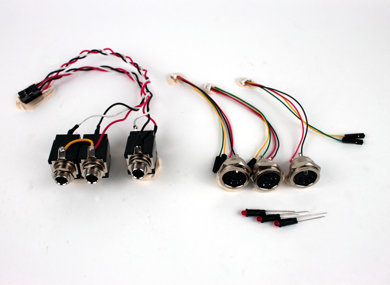
In the build-instructions there is no mention of where the wires for the audio-in jack need to be soldered. There are 8 connections on it so I need directions there
(Still open?)Another problem:
On the mainboard I soldered the 36-pin rbp-i connector with the short pins sticking out on the top (the printed side). Is this wrong? It was hard to see in the pictures and there wasn’ t anything mentioned about orientation in the wiki. Later I discovered pics at the end of the manual that looked like I might have done wrong.
Another small problem: Accidentally I soldered one 100nf capacitor upside down into the board (ceramic side is sticking out from under instead of above . Despite trying several times trying with a solder sucker I don’t manage to remove it. Now I’m considering just leaving it there, and bending the connector legs so I can solder it on there. Would the circuit still work with a capacitor sticking out on the wrong side? Hope it’ s all clear. Thanks!
Electrons have no sense of orientation so it will make no difference at all in fact it might make fitting it in a case easier in some circumstances. Just check for short circuits!
Mind you the sense of self loathing will return every time you see it!
If it makes you feel any better I have two encoders with connectors the wrong way round on one. . .
Thanks for your reply wyleu, then I can tick that one off the list! Also for your empathy regarding personal self-esteem and electronics
Remains only the audio-in question
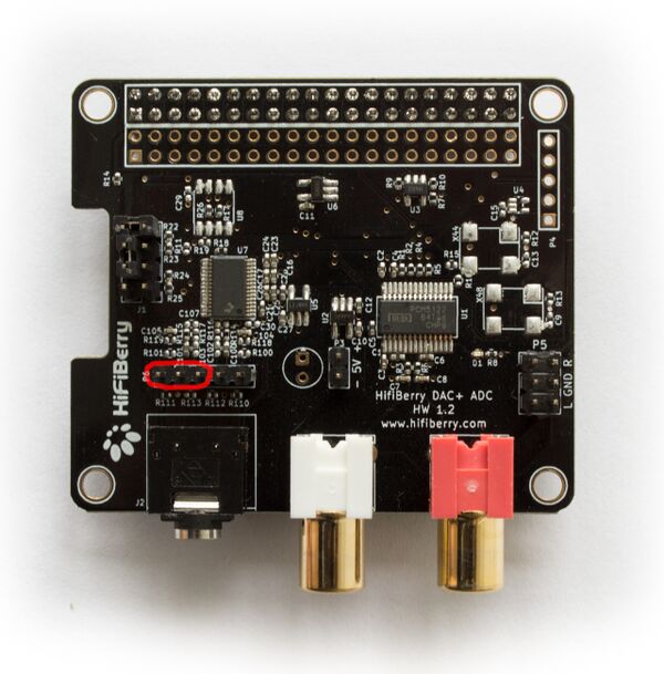
Audio in is a recent addition to the official zynthian kit and I’m assuming you are using rhe hifiberry3 adc + dac. Now I haven’t read the wiki in relation to the input side (but I will very shortly) and there does appear to be a 5 pin connector that deals with BALANCED input which is more of a concern to professional audio. (it’s a clever technique that sends a signal and an inverted copy of itself which is combined at the input. So if hum for instance is present then when the two signals are added together the hum cancels out. This allows you to send signals a long way throu electrically noisy environments). The other input which is unbalanced is via the 3.5mm (I don’t do imperial measurements) so that’s probably the connector you want. I seem to remember that the audio in 6.5mm (oh all right 1/4") jack on the zynth kit is mono so I will have a look and see if I can work out what’s going on.
If you’ve built under v2 kit instructions then Audio In doesn’t eist as a concept . . .
The v3 instruction set does a fairly detailed breakdown.
But in essence as far as audio in goes. . .
3.5mm input jack is the hifiberry’s on board input, which doesn’t need any wiring, and ( just to annoy Rees-Moog…) The Audio IN jack on the back socket (1/4" ) is a balanced input with
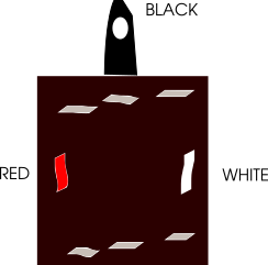
So the back socket is a balanced pair presented as 1/4" jack,
Ov - Outer and screens
Tip - Balanced Hot
Mid - Balanced Cold.
If you plug a good old fashioned Mono jack in then you will just provide signal on the hot pair of the balanced input, but rather cleverly by the design of the stereo input jack you can earth the cold side, so when the input comes to being converted it effectively appears as number which is exactly half of what you’d have got if you’d provided a balanced signal. (There’s settings for that )
So you can plug a mono guitar in and should hear something.
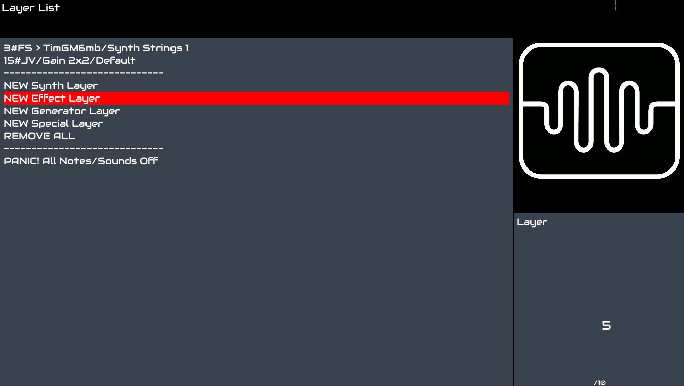
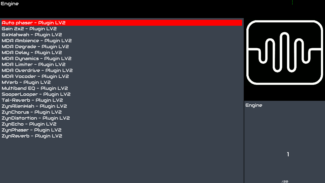
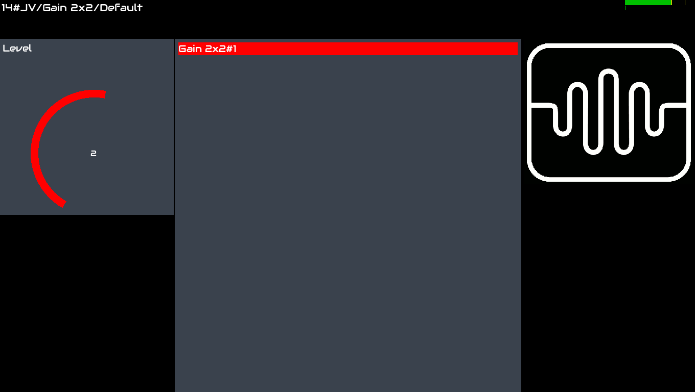
Bringing the external audio into the zynth world is down to making it an ‘engine’.
Rather than adding a Synth in the Layer List display …
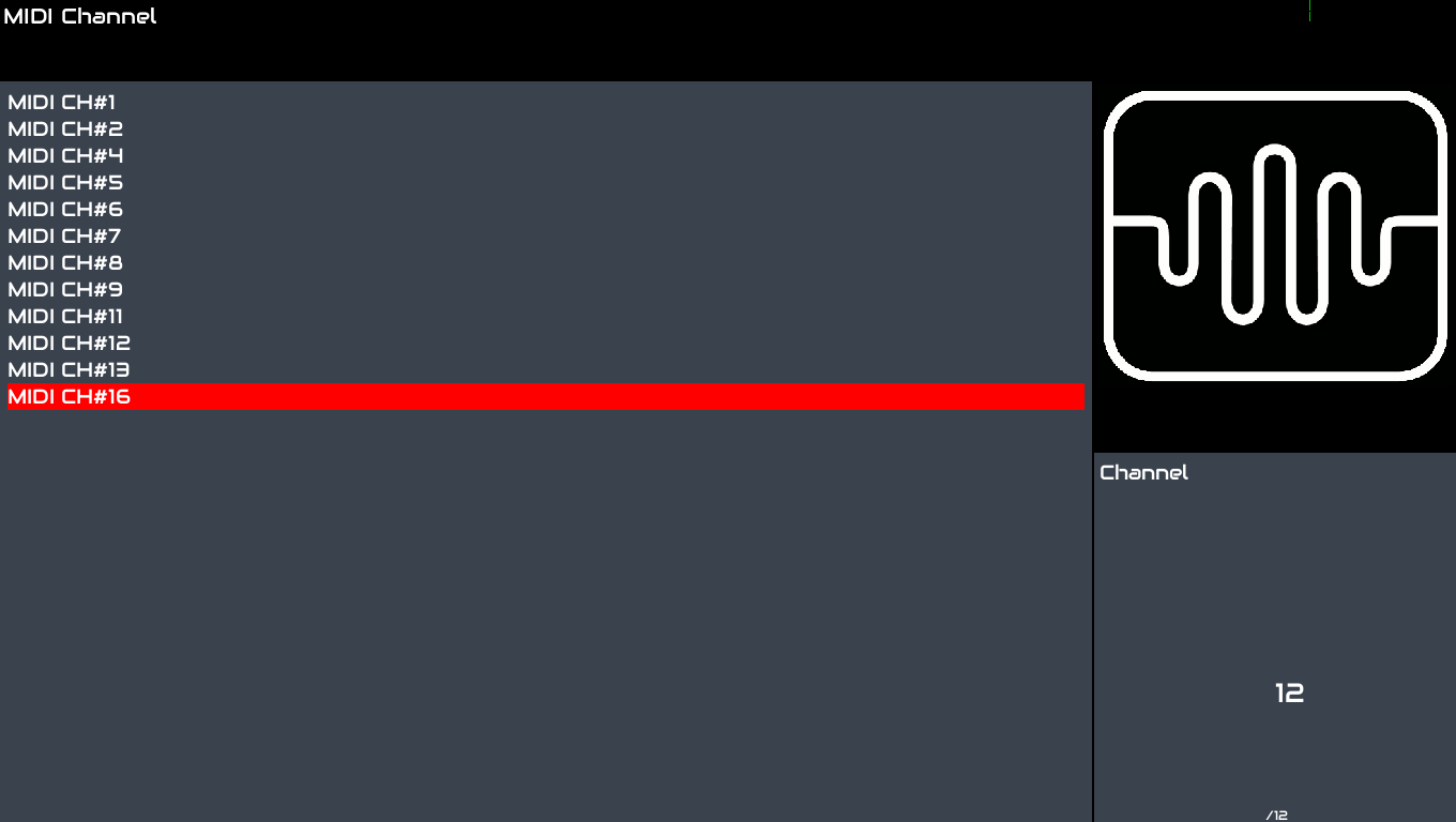
Then grab a completely erroneous MIDI channel . . . Presumably one might control the LV2 Plugin from this specified MIDI channel via external MIDI controllers, ( You know something like a harp… ).I’ve already grabbed MIDI 15 for an input effect so that’s not available
( A VERY NICE interface feature that auto allocates your Events and Engines when you build zynth environments to specific MIDI channels. 16 valid channels looks like a fine piece of MIDI specification foresight.
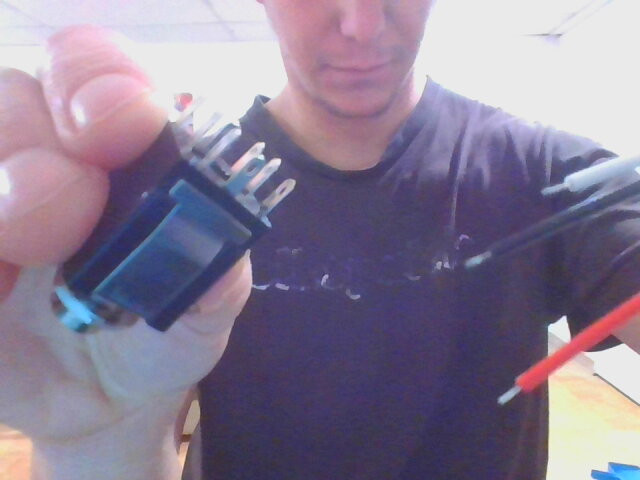
Hey Wyleu, thanks for the extra instructions. This sure gives me all the way to go once I have the audio-jack wired, but misses my actual question. No in the v2+ kit the red/white/black wires aren’ t soldered to the audio-jack yet.
Where do they need to go?
@mheidt yes, that is the picture for the audio-out jack(s). The audio-in jack looks different however and has 8 connection points on the back instead of 2.
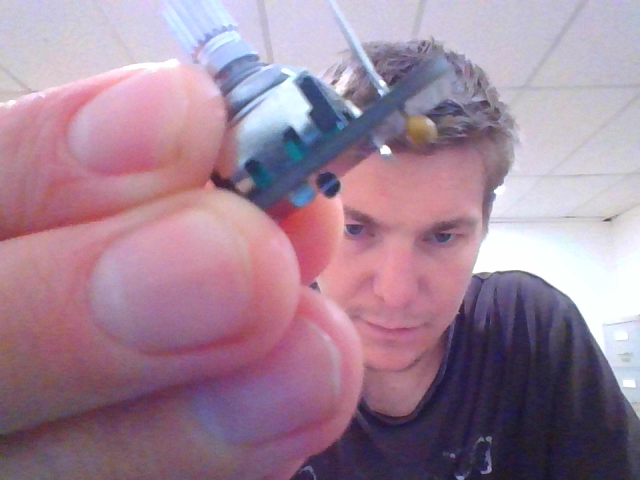
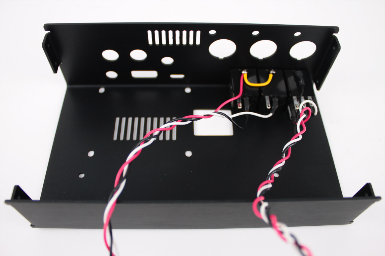
Update: I finished building the box in the meanwhile leaving out the audioin-jack just to check if I did right. What I mentioned in my first post seems to be still an actual problem. The connector-cable attaches to the mainboard only very loosely. When I boot the Zynthian (whether the cable is attached to the mainboard or not) the 4 controller knobs don’t work, though everything else does (audio/midi).
I think I might have done the same thing wrong as this guy Module PCB: solder side problem?
Does the side of where the longer pins stick out really matter that much? Wasn’ t clear to me what the upper or lower side of that part was.
The controller knobs look like they’re all soldered right as in the pictures, so I think the problem isn’t there.
The Audio connector itself can be a clever combination of stereo jack plug AND plug controlled switches. I’m assuming you have a multimeter and as such a little investigating of the socket with a stereo jack plug with the covered removed will tell you a lot about what connects to what in the socket.
For instance they often have a break on plug in terminal.
This is where you would connect an alternative input signal that is selected if there is no plug in the socket. Really simple mechanisms generally consisting of the bit of metal that makes connection to the plug is lifted off the terminal as the plug is inserted.
This is exactly how the 3.5mm stereo jack on the HifiBerry in board works.
So External if nothing plugged in,
Connector when plugged in.
Many people learn about these by soldering the signal wire to them and finding that it all works perfectly till you plug something in . . . .
So a good prod around with a plug will tell you what goes where…
The outer ring isn’t even switched in most such plugs (although there is a large plastic mounting that does it, that I haven’t seen in a few years). But you probably don’t do that as it’s earthed via the aluminium case.
So you want to ensure you have a connection from your opened 1/4" jack plug throu to the connectors that plug into the balanced terminals on the HiFi Berry …
You are right and the tutorialsays nothing about how to solder the cable to the stereo Jack connector. I will try to solve it ASAP. Until then, i will explain it here:

 . Despite trying several times trying with a solder sucker I don’t manage to remove it. Now I’m considering just leaving it there, and bending the connector legs so I can solder it on there. Would the circuit still work with a capacitor sticking out on the wrong side? Hope it’ s all clear. Thanks!

 . .
. .
