Hi !
I don’t think i’ve missed something in the wiki about that but, can we have more explanations on what do what into the http://zynthian.local/hw-audio/mixer controllers ?
Like, what is the main differences between
ADC Left
Digital Left
PGA Gain Left
and what should be touched and what shouldn’t ?
These are the settings that the audio card presents as it’s controllable options. They are, effectively the mechanisms that alsa presents before it all get’s bound to the jack server.
My last official kit was back in the V1 days, before we had audio input, and it these options were seperated off so the core of the system all behaved the same way. I don’t know if you have a hifiberry card or zynthian constructed card, so that is probably the first thing to define.
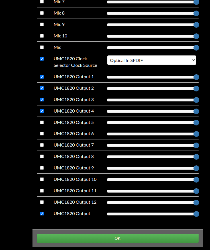
The actual presented controls are defined within the webconf audio settings and you can enable and disable them.
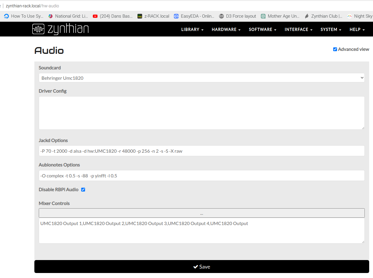
Here are the settings for my Behringer 1820 connected machine in the audio section.
For instance in this particular case I’ve turned on the Clock Selector option, after I entered the dialog, as I want to be able to select The Optical SPDIF input as the controlling clock source.
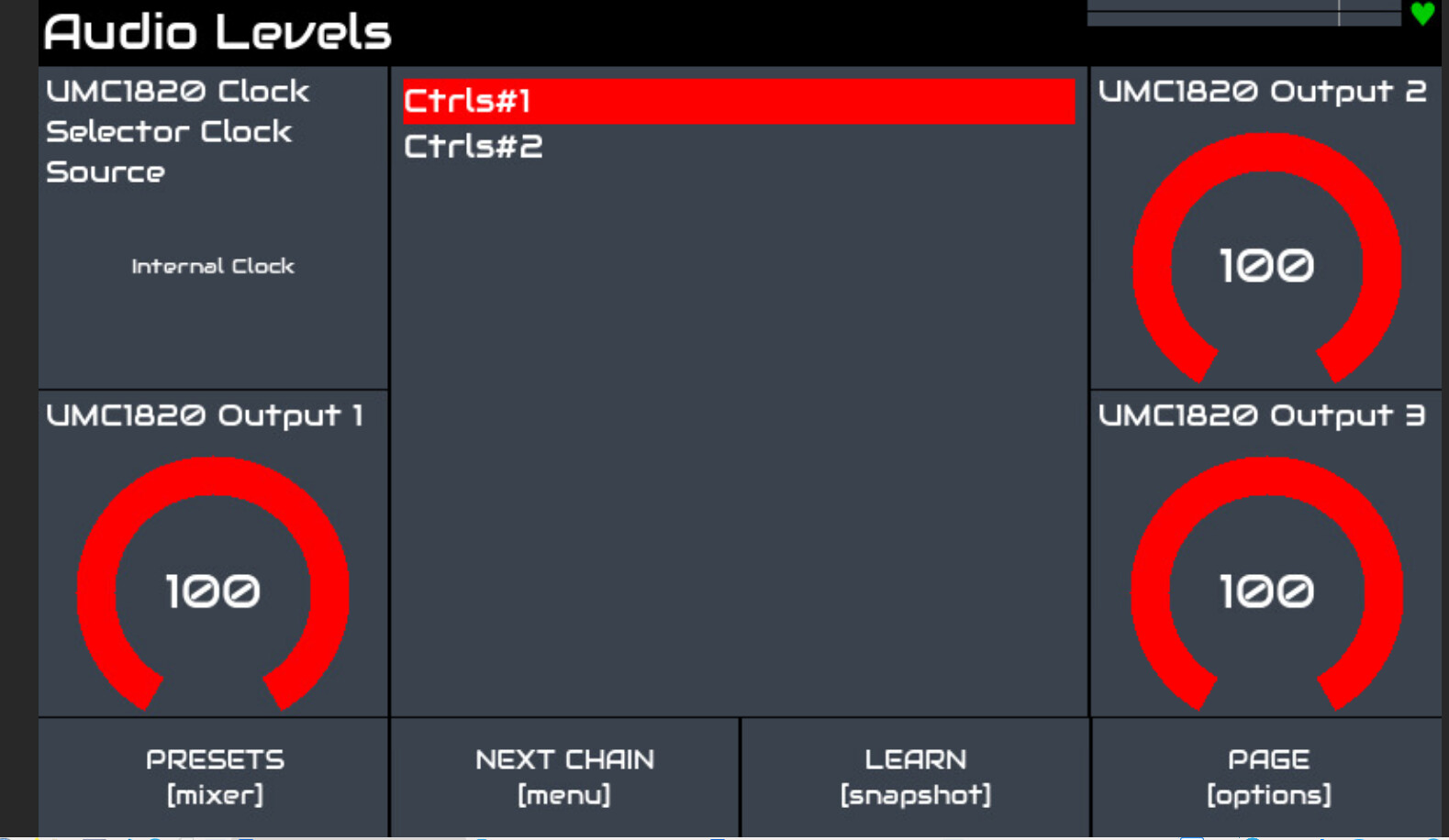
and thus it appears in the GUI…
You are right that the official soundcard should be better documented. Here is what I remember, i.e. it may be flawed:
ADC Left - Level adjustment of the left input
ADC Right - Level adjustment of the right input
ADC Left Input - Configure left input connector:
No Select - Disconnect input
VINL1[SE] - Tip & sleeve single ended/unbalanced
VINL2[SE] - Ring & sleeve single ended/unbalanced
VINL2[SE] + VINL1[SE] - Tip, ring & sleeve single ended/unbalanced
[VIN1P, VIN1M][DIFF] - TRS differential/balanced
ADC Right Input - Configure left input connector:
Same options as ADC Left Input
Digital Left - Level adjustment of left output
Digital Right - Level adjustment of right output
PGA Gain Left - Gain adjustment of left input
PGA Gain Right - Gain adjustment of right input
Note that the gain adjustment allows coarse control of the overal gain of an input, allowing configuration for line, mic, etc. The level adjustment is an overal 0…100% level.
The input connector configuration can be useful for a few variations:
Balanced signals on TSR - [VIN1P, VIN1M][DIFF]
Unbalanced mono on TS - VINL1[SE]
Two unbalanced (e.g. stereo) on TSR mixed to mono - VINL2[SE] + VINL1[SE]
VINL2[SE] is unlikely to be useful for most people but maybe you have a stereo signal on TSR and want to pick up the right channel only.
There are many other settings that are disabled by default and can be enabled in webconf but they are probably unrequired and it seems too much effort for me to document all of those|
[Edit] I have added this description to the V4 user guide. It could also be added to V5 but I didn’t want to touch that as I don’t know how we are porting the common (V4/V5) docs across. Anyone feel free to validate this description and update.
PGA gain is a gain setting, not a percentage. You would normally configure an input by adjusting is gain so that the peak input signal is below maximum permissible level (e.g. before clipping) then use the level control for fine adjustment. Here you can think of the PGA gain as configuring the amount of gain required to boost (or attenuate) the input to match the line level that the rest of the circuitry requires so a mic or guitar would want more gain than a synth or tape player. We have the Zynthian mixer for setting individual levels so I tend to adjust the gain and leave input level at max.
It is up to the user to decide what level to set the gain based on the use they intend for the input. Automatic gain control (AGC) is not a good thing in this context.
If you configure both inputs as T+R then you can have 4 audio sources mixed to two Zynthian inputs. You don’t get 4 discreet inputs but it is a useful feature of you want to mono a stereo source into one input. I like this configuration because a mono TS will work as well as a stereo TSR. There may be a level difference but that is easy to fix as described above.
ADC Mic Bias wasn’t enabled on the Zynthian I was looking at so I assumed it to not be exposed by default. It allows a bias voltage to be applied to a condenser microphone. This isn’t 48V phantom (which with be nice). It’s a low voltage used by cheaper, unbalanced condenser microphones.
I just implemented a mechanism for having “translations” of ALSA Mixer strings. I added translations for the “official” soundcard that uses the Hifiberry driver, but the mechanism is generic, so other soundcard drivers can be translated easily.
Sorry for being lazy with this, but i didn’t want to implement this dirty solution. Anyway, it’s already done and … OK … it’s dirty, but it works quite nicely and solve the problem.
So yes, @riban , i hope this is the last time you have to repeat this.
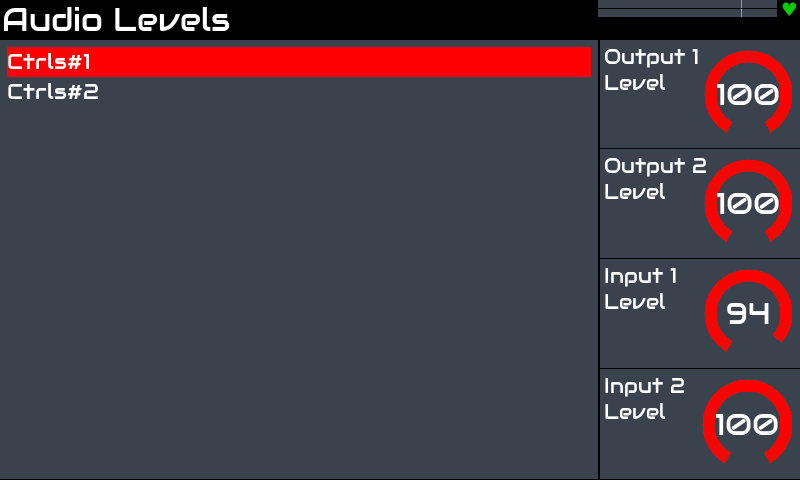
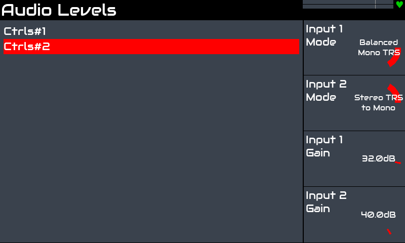
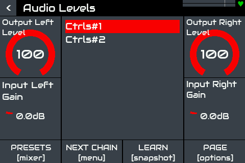
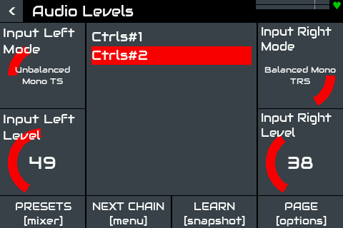
I added some specific code so the alucase printings match the texts in the display. For instance, it will be shown differently in V4 because output and input are labeled as L/R, while V5 labels are 1/2.