Hello! just got my kit in and putting it together
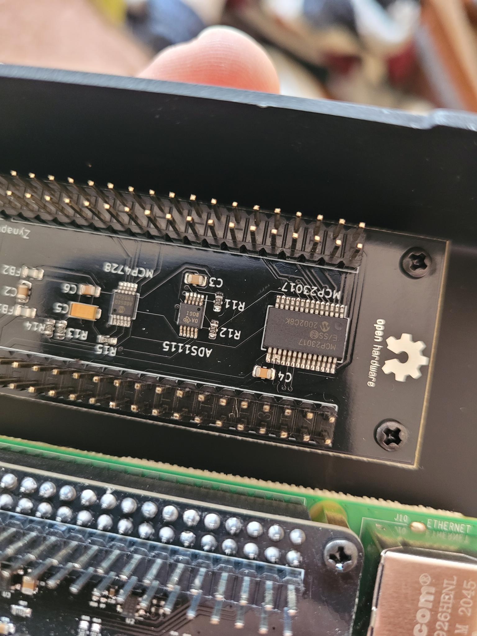
These two pins on the MCP23017 board are not supposed to be bridged correct? just want to make sure before I remove the bridge. thanks!
These two pins on the MCP23017 board are not supposed to be bridged correct? just want to make sure before I remove the bridge. thanks!
I don’t have the CAD program needed to view the official universal board schematic.
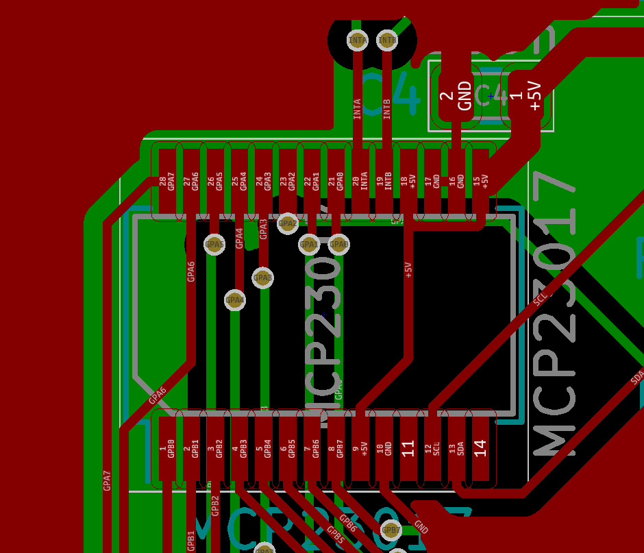
One unknown version PDF schematic floating around shows those 2 pins: I2C - A1 & A2 to be grounded as well as A0 (Pins 15-17; all grounded) which would be a legit address setting setting, the easiest to design in default setting,
I can’t speak authoritatively, but it’s not likely to be a smoke generating situation.
Hi @mikeymasonic !
These 2 pins are correctly bridged. The PCB files are published in github, but here is the detail:
Regards,
Thank you both for your help! I should of thought to check the github! I spent a bit of time trying to remove the bridge before anyone replied only to notice that there was a connection on the PCB there, whoops!
I have my Zynthinan all put together and it’s working great. Incredible work by everyone involved, this thing has exceeded my expectations. I had a blast with it and a bunch of midi controllers last night.
I have this looping patch I made in Max matched up with a midi foot switch pedal I built awhile back, I’m going to attempt to recreate it using PureData to see if I can get that rolling which would be really cool for me. This thing is really showing me I don’t have to lug around a laptop everywhere and I’m loving it so far. Thanks again ya’ll!
Such joy! Such effort! and such a complete absence of ![]()