I could use any pins but I wanted to be as near the schematic of V5, to be sure.
Sorry if I tap on your nerves with my lots of questions + suggestions.
It’s only so that I feel better when I can see all the parameters and be sure everything is correct.
But @Jean-Claude_Feltes! You can see all parameters in the V5 schematic. They are hardcoded in the V5 config, so you only need to worry about hardware when building a V5 clone. And no, there are no errors in the schematic. The V5 schematic is for a PCB that is produced in bulk, and tested hundred of times. It simply works OK.
If you want to introduce variations, then you have 2 options:
-
Create a hardcoded config (zyncontrol_xyz.c file) for your hardware, derived from V5 config. Some users followed this path in in the past (mini_v2, for instance).
-
Stick to the much more flexible VX hardware design (Custom!) and configure your hardware from the webconf panel. The only limitation is that you can only have 2 x MCP23017 (instead of 3, with V5).
Kind Regards,
Yes, you don’t need a Zynaptic. Use the V5 schematic and the V5 config.
If it doesn’t work you have done something wrong.
I was not suggesting that the schematic or the software were wrong.
Only when I’m working on electronics or software, I want to doublecheck everything, really everything.
I also want to UNDERSTAND what I’m doing, that’s why I invested time in looking at the source code also.
I believe that you have done your best, but what could I do? Check my board, check the configuration, I even used i2cdump to see if the registers are configured as inputs with pullups. Yes, they are.
I suppose the error is somewhere in the interrupt system.
Surely there is somewhere a very stupid error (as nearly always), and I want to find it and get to the relaxed feeling when the error is hunted down.
Kind regards,
JC
1 Like
I came back to my first attempt with just 4 encoders, no buttons.
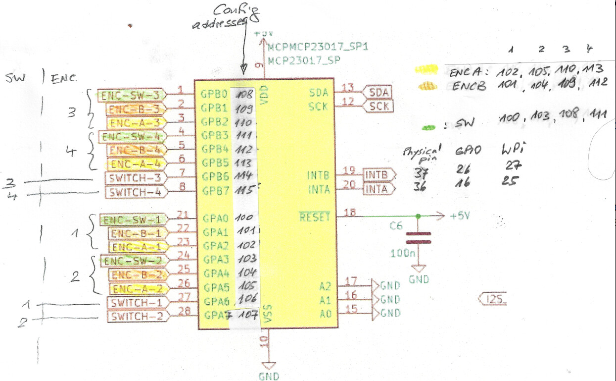
This worked with setting MCP23017_ENCODERS_V5TOUCH as I found it in the Wiki.
It was not clear what all these -1 were for, and I was not sure anymore how many there should be.
This brought me to try MCP23017_ENCODERS and omit the -1
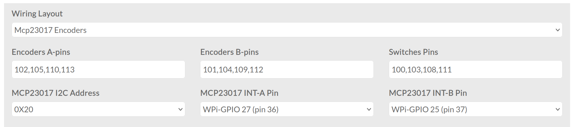
And guess what: it worked!
The log showed:
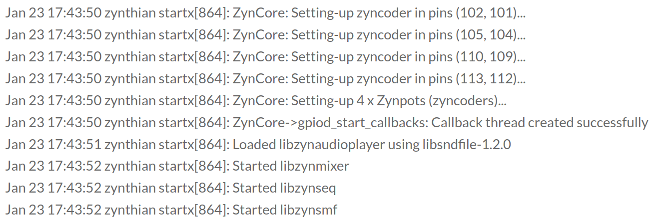
and best of all, there was a reaction to my encoders.
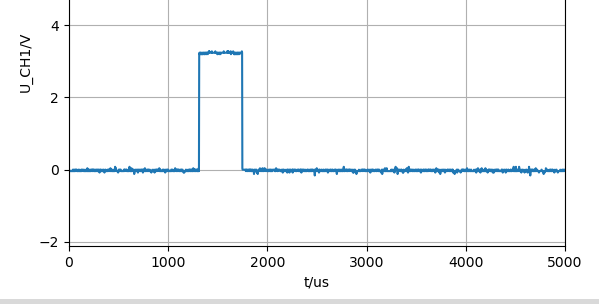
As I am curious and as I suspect the interrupt system of my non working Zynthian to be the problem, I wanted to see the correct interrupt signals on my now working one.
The oscilloscope showed a reaction when turning a knob, and a fast acknowledging with resetting the interrupt pin via I2C I suppose:
1 Like
By the way, the above configuration works also for wiring “Custom”.
As one should expect.
That makes me optimistic for continuing…