Now how do I get that?
Can I download the new version (I hope not the whole SD image, but the interesting part only) or does it come with updates (I tried an update, it worked, but I did not see the new part in the web config)
Can I give you a suggestion?
I don’t know if it is difficult or much work to change, but I would let the user choose a wiring layout, and that would directly appear in the web interface instead of being coded in the dark corners of the software (I suppose I have located it somewhere by grepping, but i still have to throw an eye on that).
Have I been clear enough?
The procedure would be: choose e.g. “V5” and everything (addresses, pins etc.) would appear in the webconfig so it could directly be compared with the used schematic.
I love my lab equipment! Using the oscilloscope I noticed that the I2C pins were down. The reason was a hair wire touching between SCL and SDA (I love flexible wire, but they more than once caused this kind of problems for me). A magnifying glass helps!
After removing this short circuit I got i2cdetect to show the addresses 0x20 and 0x21 correctly.
And I have discovered now that there is a big source of information here
that I hadn’t seen before. I am hopeful to get all this going !
If you wired like V5, then you can select V5 wiring and all mcp23017 parameters will be hardcoded. If not, you should select custom and configure adresses and interrupt lines by hand.
V5 has 2 x mcp23017 + optional zynaptik mcp. The configuration for the 2 mandatory mcps is hardcoded. The optional zynaptik one is configurable.
With other configurations (mcp23017, custom) you have 1 x mcp23017 + optional zynaptik one. You have to configure everything.
The webconf panel will show the configurable options, hiding what is hardcoded.
That means:
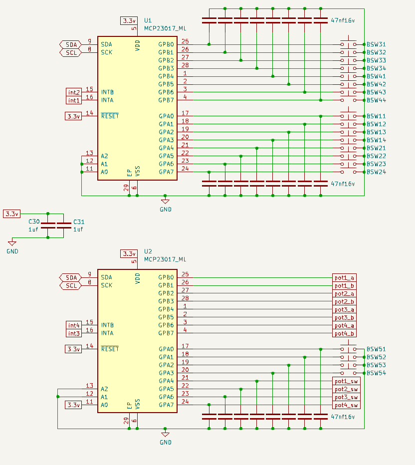
encoders on address 0x21
buttons on address 0x20
This is in contradiction with: “the first MCP (encoders) has always address 0x20, the following 0x21 and so on”, as it would have seemed logical to me and as I have read here, and as I have seen somewhere in the source code.
I have no problem rewiring my board and add jumpers to select different addresses.
If only I had a fix point of view to rely on.
I checked the KiCAD board files, they correspond to the schematic.
So effectively the button port expander U1 has 0x20 and the encoder port expander U2 has 0x21.
So the WIRING should be “V5”.
The input signals on U1 and U2 are OK.
The interrupt outputs also show reaction, going low when there’s a change on the corresponding port.
They go high again when there is a change on the other port.
Is that a correct reaction?
Now I suspect the Raspi to not correctly responding. I will check the interrupt wiring.
These informations are great. You might also want to look into my building docs, which contains a lot of information primarily given by all of this lovely community including the person who i consider being the author of your above mentioned guide.
You might know that, but the 0x20 chip it the one where “A0” is wired to ground and 0x21 is the one where “A0” is wired to 3.3V+ (Unless you got a chip with other address mechanisms like jumpers). That way you can identify the right MCP and configure accordingly.
Hi Hannes,
in fact I started with your building notes that are very fine!
I succeeded in getting my Zynthian with just 4 encoders to work, not at last thanks to your contribution!
Now I am doing the exercise for 4 encoders and 20 buttons.
A friend of mine has a Zynthian 5.1 bought as a kit and he recommended me to use the V5 schematic, than it should work out of the box.
That’s why I changed my controller board.
Unfortunately untl now I’ve not got the controls to work.
There is no error message in the log, and the sound and touchscreen work (though I’ll have to calibrate the touch)
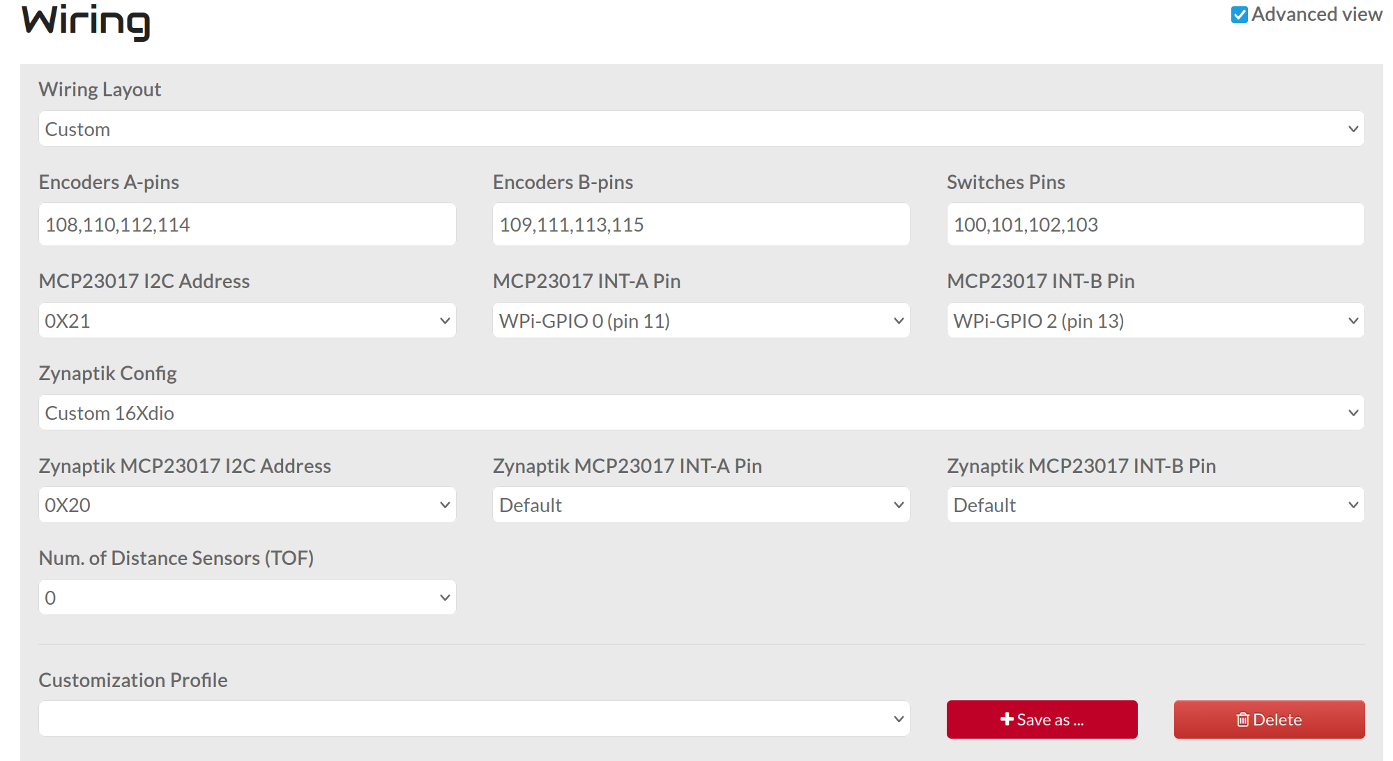
It is really nice that you can select everything, and you see what you are doing.
If you could provide an interface that would show the parameters like this, also for the hard coded standard options like “V5” etc., I think it would make things clearer and easyer.
However I encountered a problem:
V5 as I see it in the schematic and as I have wired it has for the Zynaptic MCP on 0x20 a connection as follows:
INTA = int1 on pin 29 (WPi21)
INTB = int2 on pin 31 (WPi22)
But I cannot select these in the INTA/B fields of Zynaptic. The only selectable ones are pins (7,11,13,15,16,18,22,36,37)
I don’t know if this helps: you correctly identified the given GPIO pins in webconf dropdown as the physical pin number and the WiringPi number.
I think (!, don’t take it foe granted) that the set of pinouts for the Int connections is purposefully reduced due to typical GPIO usage of other related devices like audio hats (HifiBerry and the lot), MIDI I/O and other stuff. So you might be most save using these.
That said, I don’t know exactly what would speak against using the pins you suggested. On the other hand the widely used and selectable pins 36/37 would conflict with the newer Hifiberry 8x boards. Maybe it’s worth a feature request for replacing the dropdown selector for a dedicated numerical input field.
V5 config is hardcoded and it will always be hardcoded. Don’t need config options for hardcoded parameters. You simply have to clone the V5 schematic. That’s all. If it doesn’t work it means your electronics are not the same and it’s not a V5 clone.
If you want to configure things, then use “custom” config. It does exist and has a name for a reason, right?