Well working it out . . .
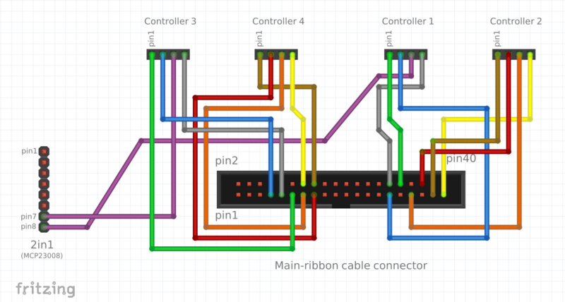
Controller 3 is connected to GPIO pins 11,7, 7(2in1) and 9,
Controller 4 is connected GPIO pins 16, 15, 13 and 14
Controller 1 is connected GPIO pins 32,29,8(2in1), and 30
Controller 2 is connected GPIO pins 38,36,33,39 .
of these 9,14,30 & 39 arre grounds from the Raspberry pi GPIO pin diagrams
Looking in the config data of the non current file zynthian -gui.py than comes straight from the pre burned image you see:
hw_version=“PROTOTYPE-4”
Controller RBPi connector upside / Controller Singles
elif hw_version==“PROTOTYPE-4”:
zyncoder_pin_a=[26,25,0,4]
zyncoder_pin_b=[21,27,7,3]
zynswitch_pin=[107,23,106,2]
select_ctrl=3
Thee don’t seem to match but there is a layer of mapping that, perhaps, isn’t obvious.
This is because to the Software there are virtual concepts called GPIO pins which the software refers to by number and this is largely related to the CPU used on the board,
But the designer of the raspberry pi ( and indeed anyone that uses the chip) is free to map these onto a header on their board in any way that seems fit to them.
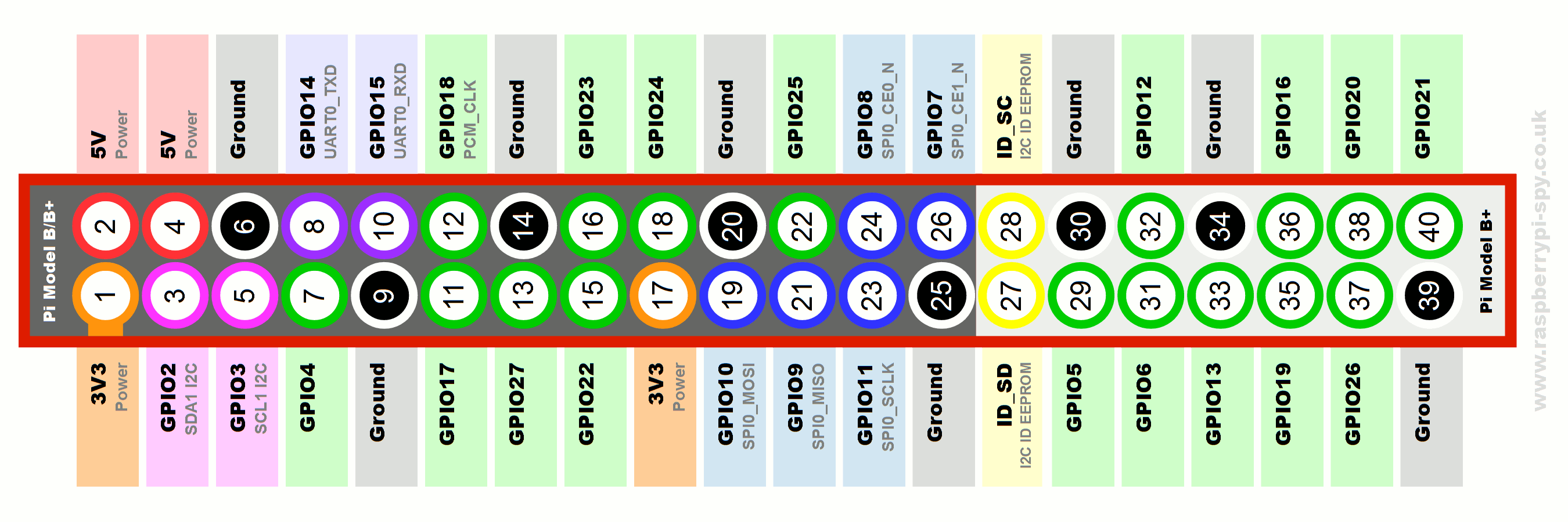
So there is GPIO map to actual physical pins that appear on, what to us, is the defacto standard set of pins.
Controller 3 is connected to PI pins 11 (GPIO17) ,7 (GPIO4), 7(2in1) (not on Rasp-pi header),
Controller 4 is connected Pi pins 16 (GPIO23), 15 (GPIO22), 13 (GPIO27)
Controller 1 is connected Pi pins 32 (GPIO12),29(GPIO5),8(2in1)(not on Rasp-pi header),
Controller 2 is connected Pi pins 38 (GPIO20) ,36 (GPIO16),33 (GPIO13) . . .
zyncoder_pin_a=[26,25,0,4]
zyncoder_pin_b=[21,27,7,3]
zynswitch_pin=[107,23,106,2]
But it still seems confused . … . Anyone see my mistake … ?
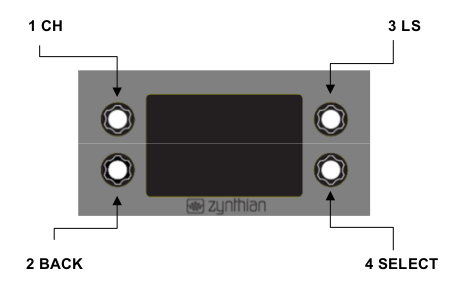
In answer to the original question
encoder 1 is Channel
Encoder 2 is Back
Encoder 3 is L/S
Encoder 4 is Select