Firstly, congratulations on a great collaborative project! I am building custom hardware loosely based on the V5 using a Raspberry Pi 5 but with a 7" hdmi + USB touch display and USB Audio output. I have built the first encoder + 4x switch board set to address x20 which works perfectly. However, I have been unable to get a second MCP23017 port expander to be detected when any buttons are pressed. The second port expander address is set to x21 in hardware, with its A and B interrupts connected to Pi GPIO pins 36 and 37. When a button is pressed, its corresponding interrupt line goes high but the interrupt is never serviced by the Pi and so the interrupt line stays high. The i2cdetect -y -r 1 command shows that addresses x20 and x21 are both detected. Have I missed something crucial in the wiring configuration?I have suffered a number of hours trying to get inspiration using chatGPT so am a bit desperate to get help from a real person! Any assistance would be appreciated.
Hi @SteveH! A very warm welcome to the family.
Please post info of your Wiring configuration in webconf, e.g. screenshot. You asked if you had missed something crucial but it tends to be a tad awkward to reconise such errors without sight of what you have actually done! 
Hi riban. Of course! I didn’t want to blitz with too much info up front. I think this is up to date…
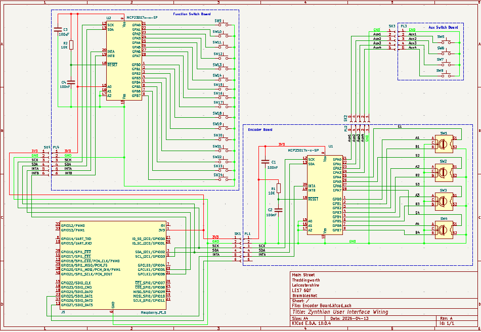
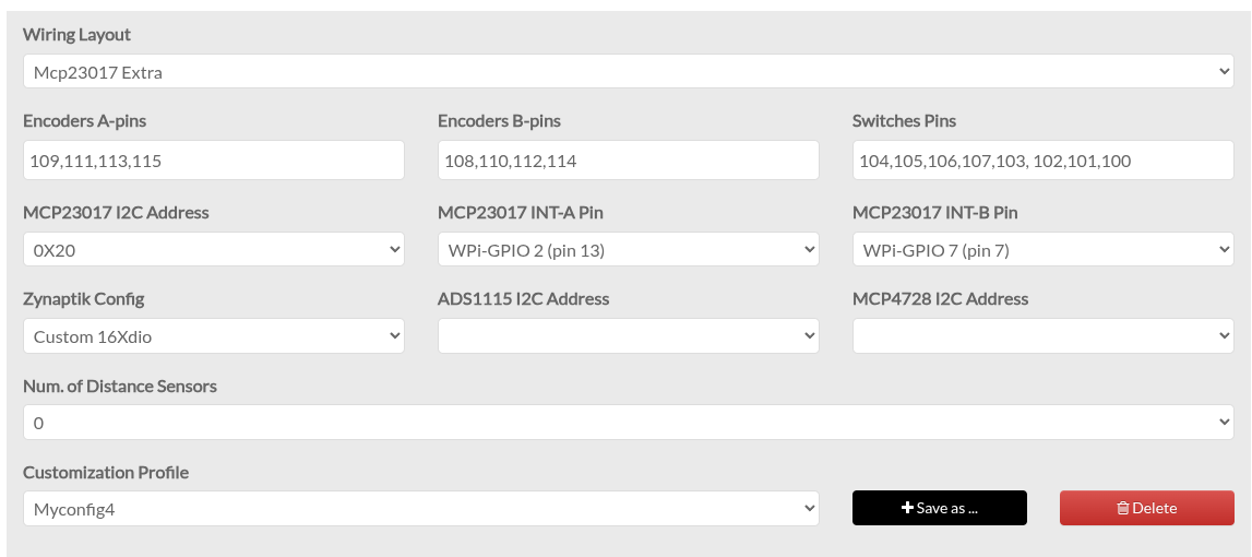
I don’t know how the second encoder is addressed in the config. I read somewhere that it’s intended to be somehow autoconfigured.
From your schematics I think the first encoder at 0x20 is connected to the pins 36/37, but your wiring config states otherwise. It might be worth noting that when something’s stated as GPIO number, you might consider that being the WiringPi number. Right now your wiring config says the first MCP might be connected to pin 13 and 7, meaning WiringPi numbers 2 and 7, even it says “GPIO”
On your schematics the MCP at 0x21 the interrupts are connected to WiringPi No. 5 and 6, which would be physical pins 18 and 22, right?
There may be others better positioned to respond, but it looks like your webconf allows configuration of a single MCP23017 but you have two. You may want to select a different wiring layout, e.g. “Custom” with “Zynaptik Config” set to “Custom 16Xdio” which then gives you fields to populate with the second set of I2C address & interrupt pins.
I have been completely confused by the GPIO port numbering! I have tried to keep to the Pi’s physical pin numbers. Is there a definitive document that relates the different numbering systems used? The expander on port x20 is connected to pins 13 and 7. This works OK. I could not find any way to define the ports used for the expander on port x21 but Googling seems to say that the Zynaptik Config automatically selected the x21 address and physical pins 36 and 37. I did try connecting the interrupt line to all of the spare Pi port lines in the vain hope that if one of them had been configured as an interrupt, it would have elicited a read of the x21 port (which would have reset the int line), but none of them did this.
From my POV this here is helpful:
The circles in the middle are physical pins, the WiringPi number is corresponding to “GPIO” on tour schematics and in the wiring config. The physical pin numbers in your schematics are wrong, it seems to not be a model of PI4 or 5.
I’ll check the schematics but at present the x20 device is using physical pins 13 (A) and 7 (B). These work OK. x21 uses interrupts on pins 36 (A) and 37 (B) which I believed were automatically assigned on the Zynaptik switch array.
I did not do this myself and also don’t have a zynthian in front of me, but how I understand the part from @jofemodo I linked above it should be not necessary to put all the 200 range numbers to the switch configuration, but when you do this:
… you may be able to configure the adress and interrupts.
Thank you for the pinout. J5 on my schematic is the symbol supplied in the KiCAD libraries. I think it looks the same as the data you sent?
I have gone this route before but when I set Wiring Layout to ‘Custom’, even with all of the Encoder pins, Switches pins, i2s address and interrupts pins set the same values, none of the encoders or switches work. The only way I could get the majority of stuff to work was to select the ‘Mcp23017 Extra’ option. Selecting Mcp23017 Zynaptik-3 say still only allows me to set one i2c address number, unless I am missing something..
Just as a matter of interest, what are the WiringPi numbers that appear on the Raspberry Pi Pinout document? I have seen them used in some of the documentation. Kind regards.
I don’t know the history of numbering standards (wiringpi corresponds afaik to a deprecated C-library), but whenever you read GPIO in webconf or your Kicad schematics these are corresponding to the WiringPi numbers in the pinout documents, and, for your confusion, not to the GPIO numbers there.
I’d be interested if you wired your hardware corresponding to the schematics you sent. Because there you use different wirings.
Also I assumed that the missing connection on your 0x20 MCP’s Int-B pin is just an accident.
Hi @SteveH !
I would recommend you to stick strictly to the V5 wiring scheme. If you do so, you will avoid a lot of configuration headaches for sure.
Alternately, you could try the latest test image. Vangelis include some improvements that allow to configure the 2 x MCP230027.
Best regards,
Apologies, the schematic was fairly early on when I thought that only one interrupt was required for each expander. I kept on changing the interrupts to try and find a combination that worked. If I don’t get a suitable solution to the added expander, I may look at moving closer to the V5 configuration. However, when I tried this originally, I had problems as I do not have the standard screen and Audio card and I was trying to work with what I already had. I still don’t quite know what switches and layout will work best with my intended work flow. I just started with the touch screen and the encoders but there were just some functions that were too difficult to access without physical switches. I may have to get into the software configuration but I am not a real software guru and I doubt if there is much in the way of documentation that shows how the code is organised. Also, any customisations would make it hard to keep updated with software updates. Many thanks for your assistance.
You refer to Vangelis. Is there any more information that you can point me towards with this please?
Vangelis include some improvements in the webconf wiring config, allowing full configuration of up to the 2 x MCP230027.
But, really, if you are building a V5 clon, stick to the V5 schematic. You will avoid a lot of config headaches. Not matter the display. Just for the controller board schematic.
Regards
I will give the V5 another try as I have a bit more experience in getting the Audio and monitor running with non standard configurations. Thanks.
You only need to focus in cloning the Control Board scheme.