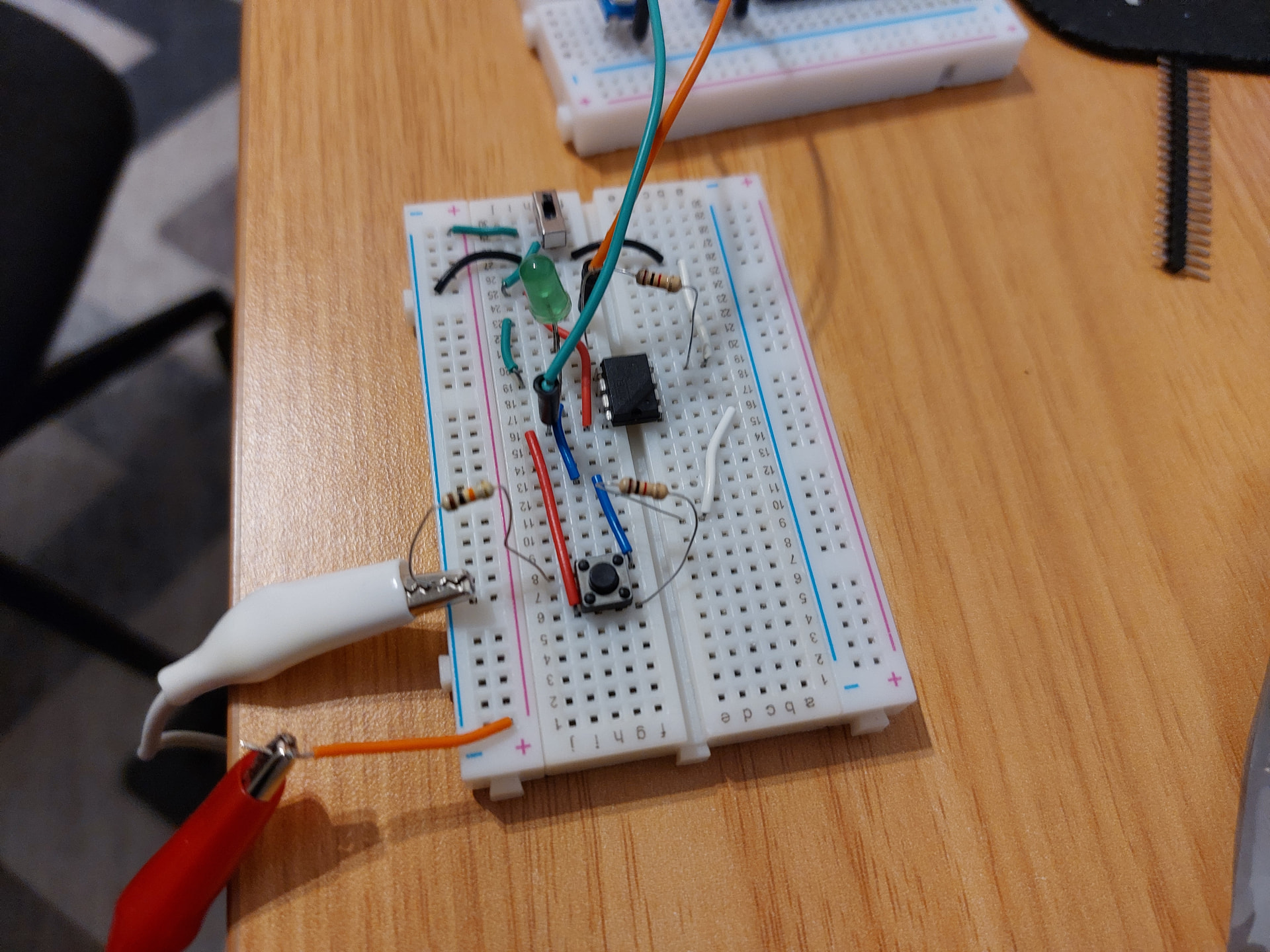
I want to create custom MIDI foot keyboard controller from scratch using Arduino or ideally ATTiny85, but with no success. I started with MIDI examples available for Arduino (https://docs.arduino.cc/built-in-examples/communication/Midi/) and community ( Notes and Volts: MIDI for the Arduino - Build a MIDI Output Circuit ). Flashed it first to ATTiny85 (software serial) and then tried to use hardware serial from Arduino, but I get no MIDI events in Zynthian input (for other controller like e.g. Yamaha MODX this works fine with zynth), so this is definitely something with my circuit or boards (I use Ali clones both for Arduino Nano and ATTiny85).
Can anyone help me with some sanity checks? Do you have any minimal credible and working schematic for Arduino or RPI? Just sending single midi message would be perfect.
At this point I am considering skipping this part with using dedicated MIDI module, but any help or guidance on getting this working from the scratch will be much appreciated.
This schematic is for MIDI in, but I need out (on the internet tutorials use 220R resistors on Vcc and 220R on TX without additional ICs). But I see that Digispark shield uses additional IC.
It is simple in principle.
The part you are missing is that your USB device must identify itself as a MIDI device (class compatible as it is called).
As far as I know the only Arduino’s that can do that are the UNO and the boards with a ATmega32u4 processor (Leonardo, Pro Micro).
The Arduino UNO uses a separate USB handling controller, a 16U2. If you want it to behave as a MIDI device, it must be reflashed. I use USBMidiKlik. Advantage is that you can switch between MIDI and HID (keyboard).
The Pro Micro I use can be programmed directly for USB MIDI if you use the proper library (MIDIUSB).
This of course applies only to USB MIDI out.
If you use a DIN 5 port you can simply use the normal UART set to 31250 baud.
        //  Set MIDI baud rate:
        Serial.begin(31250);
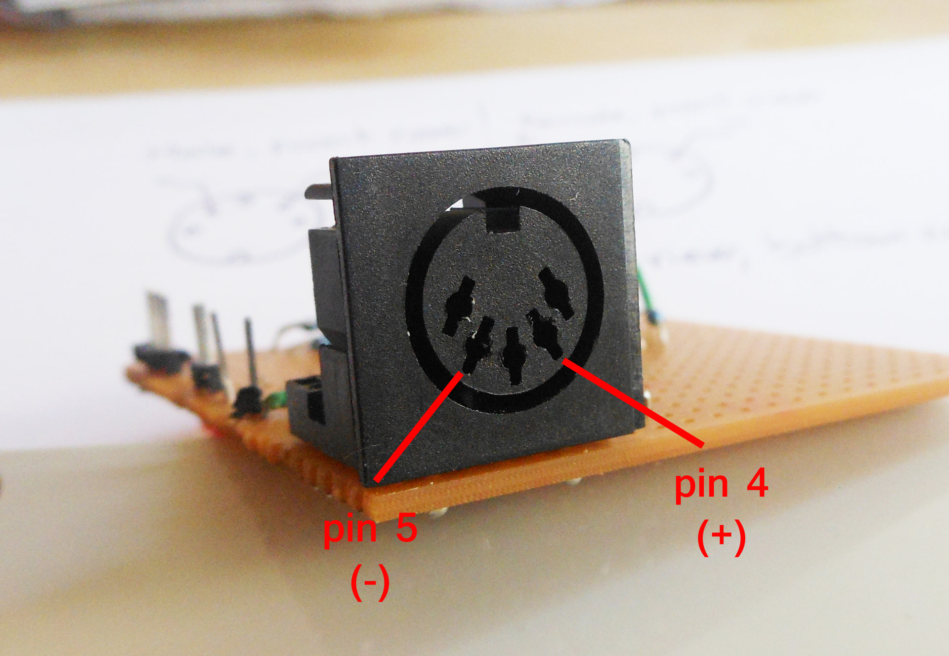
If it does not work you have reversed pin 4 and 5 (yes, happens to me all the time).
What does the RPI3 do in this context? I thought you were using and Arduino?
If you want to connect a 5V DIN 5 MIDI to the RPi3, you must use an optocoupler like @tunagenes writes.
I don’t know what to say… Thank you so much, if you hadn’t written that I would have not checked myself I was looking at the female connector schematic and wiring male one
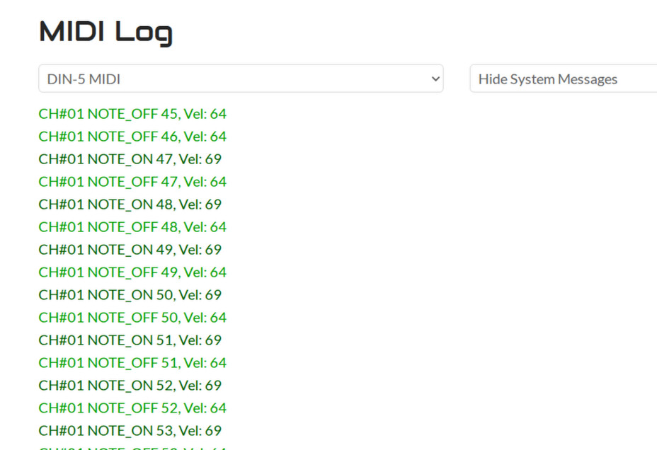
I got this finally on Nano, now trying with ATTiny, fingers crossed.
Yes it often catches me out too. More accurately, on the output pin 4 is tied to +5V (via 220 ohm resistor) and pin 5 has the signal whilst on the input pin 4 is connected the anode (via 220 ohm resistor) and pin 5 is connected to the cathode of the opto isolator.