Hi all I’m trying to build a custom Zynthian and am prototyping adding some additional buttons to the Zynthian via an MCP23017. I’ve read through every post I can find on the subject but I am still having some issues.
I’ve attached a button to ground and the GPA0 on the MCP, and a debounce capacitor between them as outlined in the schematics, and have tested with a python script to confirm that it is working. I can also see it listed on the webconf homepage, so I think the issue is related to my wiring config somehow. My understanding is that WiringPi 100 would be GPA0 - is that correct?
I’ve left encoders disabled for the moment as I thought that starting with single-pin components would be simpler
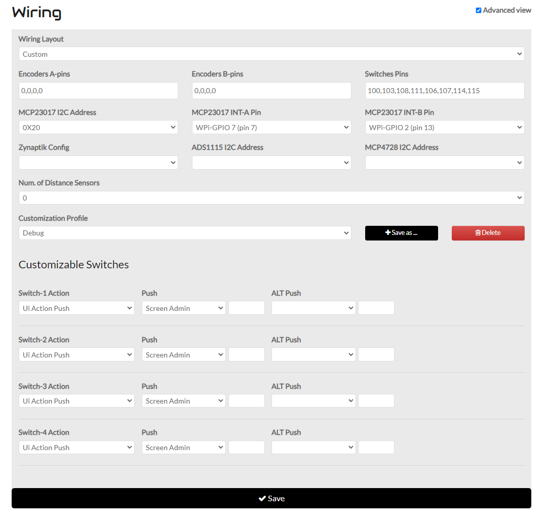
If I enter pin 100 into the “Switches Pins” box I don’t get an option to configure its action, and when I enter 8 values (100,103,108,111,106,107,114,115 - taken from one of the presets) I only get 4 customisable buttons - how does this section work and is it related to the pin numbers I’m choosing?
I also have a few other questions about the wiring interface - I’m hoping to use two MCP chips, one for encoders and one for buttons, but have read conflicting information about whether that is possible and how to do so. I only see one option in the wiring UI for setting the address for example, so don’t know how the second would be configured.
Thank you in advance, and if it helps at all I’d be more than willing to document my findings so that it’s a little easier for someone attempting this in future.
Thanks! I’ve been playing with it for a little while with just a touch interface, but am just now getting into building a full kit around it
Thats what I thought, so presumably the first MCP would be at 0x20, and the second at 0x21? What are the default pins for each on the Pi’s GPIO, and which MCP do the options in the wiring webconf refer to?
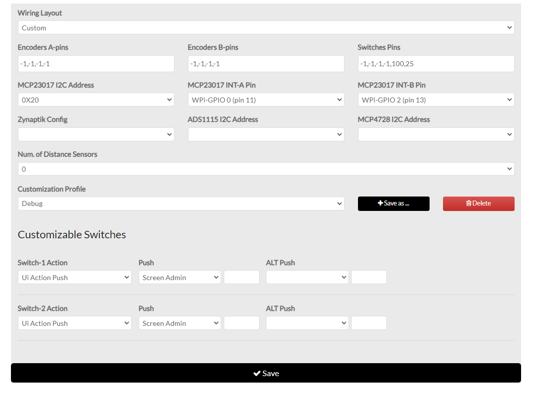
Are there any debugging tools that might detect key presses within Zynthian? As you can see above I’ve got pin 100 declared and an action assigned to it, so I’m not sure where I’ve gone wrong. To confirm, my MCP is at address 0x20. I also don’t understand why I’ve got 8 switch pins declared but only 4 switch options in the web conf, shouldn’t it be one per switch?
Thanks again, and apologies, I appreciate there are a lot of questions there.
For working with zynthian, the MCP23017 needs the IRQ pins connected and configured correctly.
For testing, you can use the test program included in the zyncoder library. Take a look inside /zynthian/zyncoder/build.
The first 4 switches are not customizable, and the functionality is hardcoded. They use to be the 4 encoder’s switches.
But they are not mandatory. They can be configured as -1.
Indeed, if you are building a custom control interface for zynthian, perhaps you want to take a look to how Z2 and V5 control boards are managed in the zyncoder library.
Thank you very much, I will have a play and report back!
I’ve run /zynthian/zyncoder/build/zyncoder_test but it hangs at “Testing switches & rotaries…”, probably because the rotary encoders are not connected. Perhaps I should abandon buttons until I’ve got the encoders working.
You should configure the encoders with “-1” to get them disabled.
Anyway, if you reach “Testing switches & rotaries”, then it’s working. From here the only thing you will see is switch or encoder activity, if any
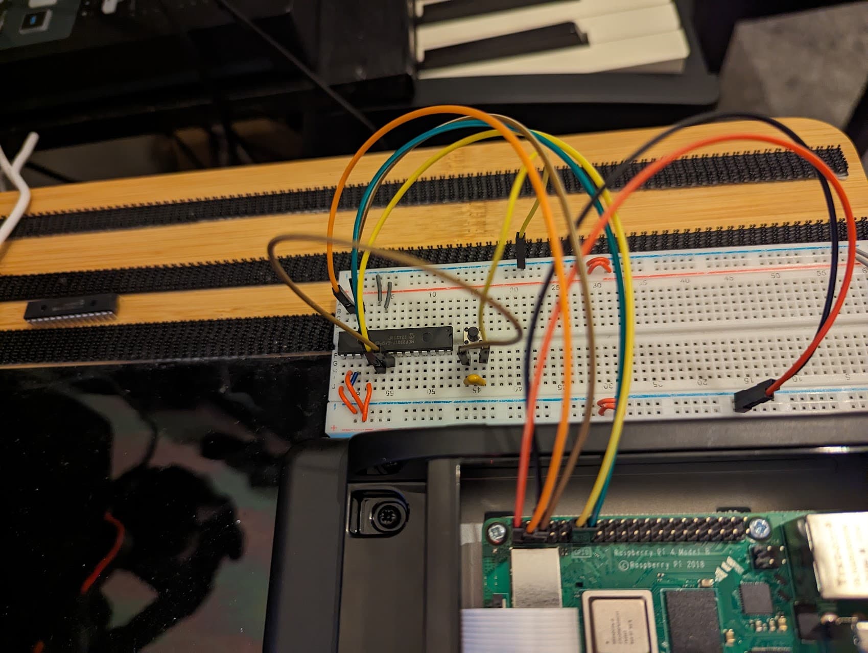
I’ve made some progress - managed to get switches on the GPIO working as expected but still no luck with the MCP23017. As you’ve suggested, it looks down to the interrupt pins.
The zyncoder test script showed output from the GPIO switch as expected but not the MCP23017, so I went back to Python and polled the interrupt pin manually and it remained high regardless. I don’t think I’ve managed to damage the chip but I have some spares in the post to rule that out.
If it’s not that, I’m not sure where I’ve gone wrong! I believe I’ve wired everything correctly:
(Apologies for the odd camera angle, it was the only way I could get the breadboard and the GPIO in frame at the same time as the wiring. Also, note the button on GPIO 25 isn’t pictured)
I’ve also since added the two 10k pullup resistors to the i2c pins from the v5 schematic, but couldn’t get another photo as clear as the one included)
No. You could use more, but you have to write a “zyncontrol” file for configuring the hardware layout. Take a look to the zyncoder repository to see some examples
On a related note, is there a “preferred” layout for the Zynthian controls for the future? If I was making my own one, would I be better following the V4 or V5 control layout?
If you mean “physical layout”, i agree @tunagenes. the 4 encoders to the right is the way. Regarding button, the V5 makes a proposal of having more buttons to have direct access to functionality, improving workflows, etc. The RGB LEDs are part of this proposal too. Anyway, zynthian is highly configurable regarding switches (buttons) and LEDs, so you could easily arrange your customized layout.
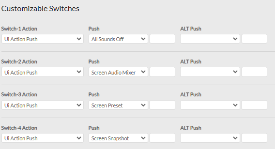
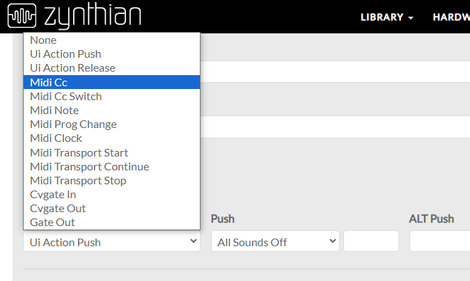
Webconf - HARDWARE->Wiring. Enable “Advanced view” and you will see the configuration for each switch. You can configure the action for the short, bold and long press of each switch. If you have an Alt key available (like V5 config) then there are configs for each of those triggers with Alt enabled too. Depending on the action selected, the corresponding fields change to provide appropriate subactions / parameters.
That is the configuration for the 4 custom switches on an official V4. If you have a custom device with more switches, you must select “Custom” kit and then add the pins for your extra switches. After saving, the extra switch configuration rows should appear.
with my V4 Zynthian in wiring configuration it seems possible set Midi CC to wire action as open Mixer screen
now I would like to use MIDI CC as button/switches in my second Zynthian (naked version) but under DUMMIES wiring layout I cannot find the Midi CC option
why?