Ok i need to buy an Iron then and burn something. I’ve very bad pulse to this things  .
.
So if someone can mod the tittle to SOLVED  .
.
Thanks for your knowledge, you’re awesome 
Well I wont modify the Title till we’ve satisfied the 


Ok ok will post here the soldering photos 
1 Like
We’d rather have some sounds
1 Like
An alternative to soldering is to buy a crimp tool and make some Dupont Y-leads or daisy chain. Of course that is a different skill set!
1 Like
This is the next step.
1 Like
Hi, it’s me again.
I make a midi in circuit to connect to the GPIO directly following this: https://www.samplerbox.org/article/midiinwithrpi
How i put it on webconfig?
And the other, need to run the phyton uart code?
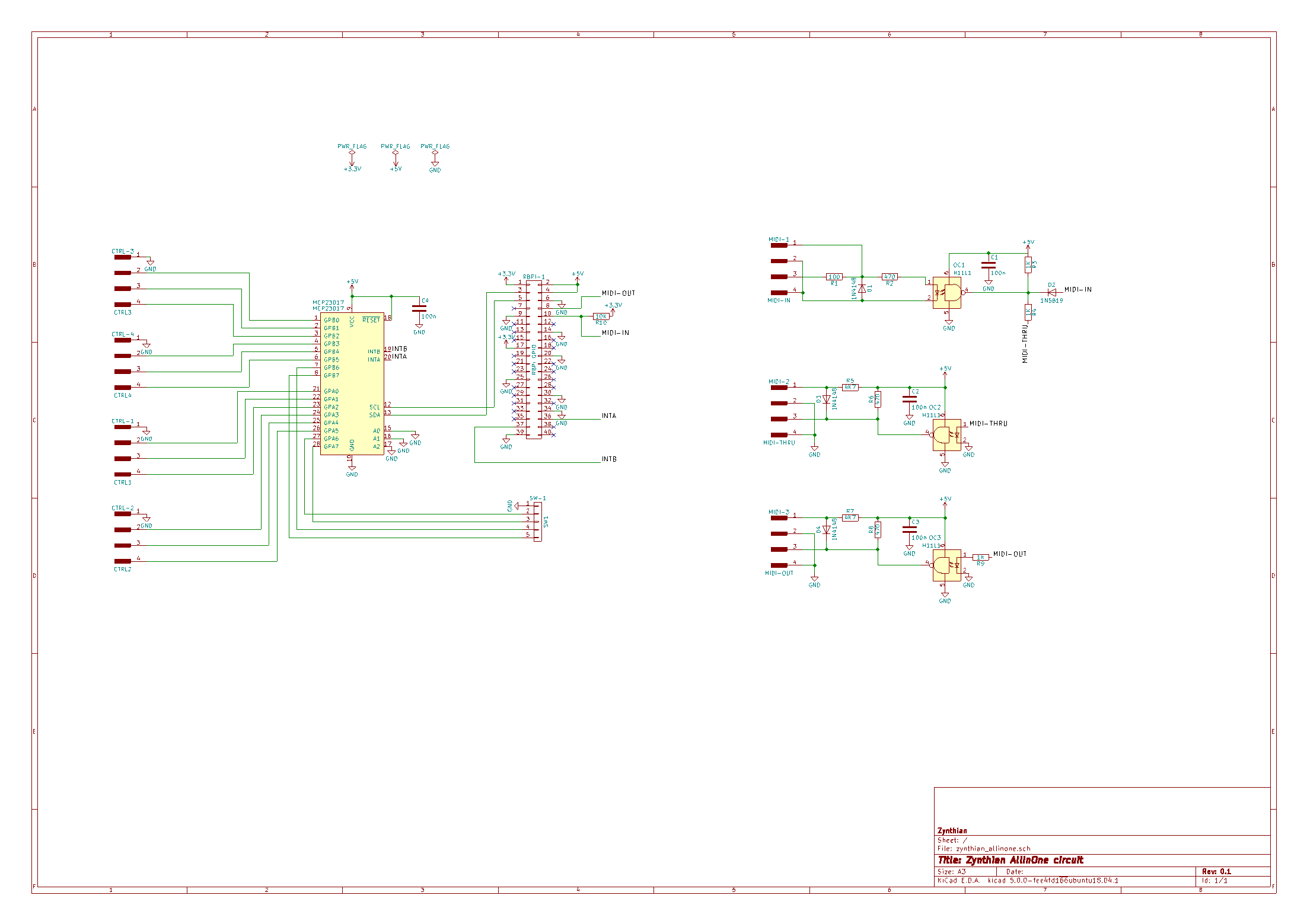
The five pin MIDI implementation isn’t really something you configure on the webconfig. You ,perhaps, will need to match up with (one of ) the zynthian implementation
for instance…
https://discourse.zynthian.org/uploads/default/original/2X/9/983f30a1a1e8cf0824b0e4fc3f71ab27aa0e006d.png
The MIDI I/O from a software perspective is an implementation of a TTY port so it’s all defined for that.
1 Like
ok, i understand. Will match the midi in circuit so. Thanks for the reply as allways. I’m so close to finish the enclosure and the Zynthian to full work.
1 Like
ttyMIDI is enabled by default on Zynthian so all you have to do is connect the optoisolated current loop to the Rx pin of the Raspberry Pi. I found the (slightly unorthodox) circuit used in the official Zynthian to work best. A traditional input circuit doesn’t seem to work.
1 Like
Yea that’s an issue for me, getting the signal from a worn sensor without a dangling USB interface.
One product specific suggestion:
maximum bus length of an I2C link is about 1 meter at 100 Kbaud, or 10 meters at 10 Kbaud.
(and less for 800k I2C)
Doesn’t have a differential drive like USB, which tends to cancel interference.
Here’s a little differential driver board, if you really had to go against the trend and long haul I3c.
Without kicking off too much of a fuss it’s the only way of getting parameter control on a remote panel of any sort at the moment…
Hello everybody,
I allow myself to enter this discussion as my problem is similar.
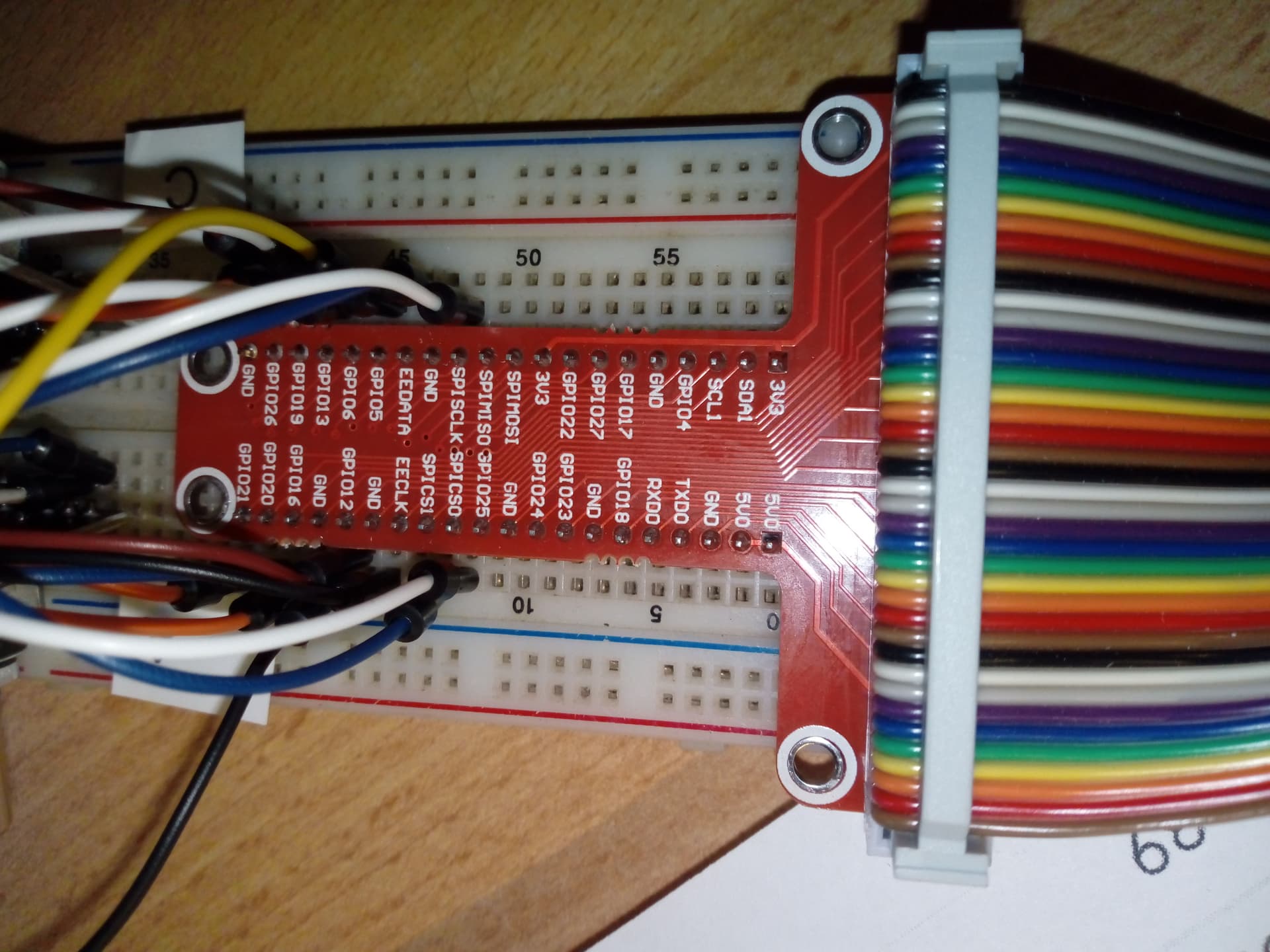
I bought an adapter (I attach photos) and I connected the four encoders following the pins of this thread … At startup it crashes on the Zynthian screen.
My doubt is that the adapter has different pins, even if with a tester I saw that they are connected in the right way … but it doesn’t work … could it be the adapter?
Thanks for any advice.
The first thing to try is to disconnect the header and set up as a dummies to see if everything can start cleanly.
IT should start up unless it’s got a display or sound card issue, which will at least rule out those possibilities.
I’ve done a fair bit of direct pin connection and I really don’t recommend it as a way going forwards. Firstly the Pi gods above our level of sanity can ( and have) changed things subtlety which have led to problems.
IT will work, but you will have to allocate the i/o pins correctly in the webconf options to get everything to function. Luckily these doesn’t tend to be a problem if it’s mis set. It just simply doesn’t work.
Dear and thank you for the lightning-fast response.
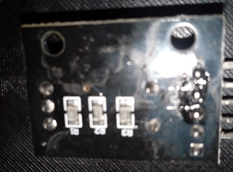
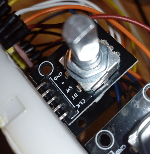
If in the web conf I select on wiring, Dummies, everything starts and works. The display, an Adafruit 2.8, works perfectly … the problem is precisely in the encoders that I have connected as in this discussion … Another clue … in my encoders there are three resistors that I have unsoldered … … is not that I had to unsolder only two ??? it would be nonsense …
This is a photo of an encoder to which I have not unsoldered the resistors.
Thank you so much for any advice
Encoder with resistors are probably the sort NOT to use, sadly. Do they mention 5V on the connectors ?
The encoder itself is all you need and the wiring can be confusing. I’m sure the encoders themselves can be connected. IT’s what’s happening on the PCB boeards that can be a problem.
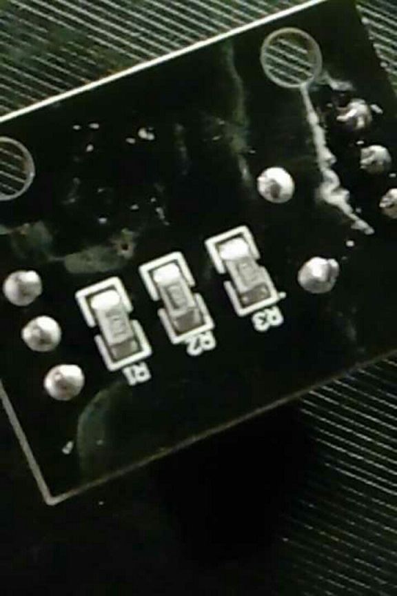
An in focus picture is probably the best way forward…
Yes, I apologize for the photo …
It does not mention 5V but only +.
However, if this is the problem, I have no problem unsoldering the encoders and connecting them without a pcb

At the limit with the capacitors on the pins …
unfortunately my phone doesn’t take better pictures and i broke the usb microscope i use for electronics …
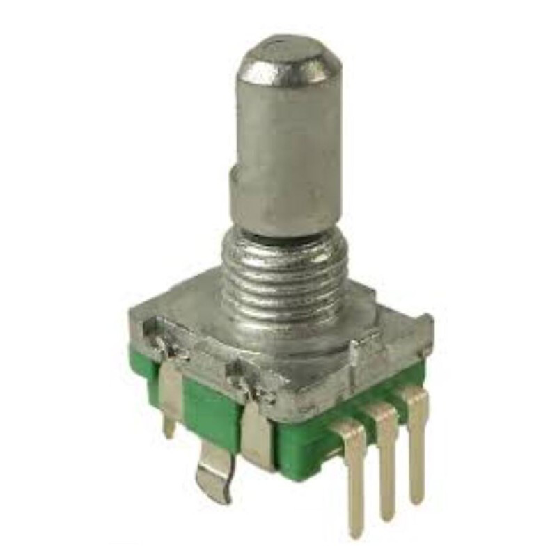
The ‘+’ connection and resistors are used to bias the encoder, i.e. weak-pull-up pins to the level supplied to ‘+’ pin. Zynthian uses Raspberry Pi 's internal pull-up so doesn’t need these.
Hi @Lanfranco welcome
A generic rotary encoder with Switch will do the job.
Just cut some Dupont wires and solder them directly on encoder pins.
There are here a couple of discussion about these ones (yours  )
)
:IMHO they sucks.