Hi Guys,
I managed to connect Encoders to the GPIOs. Carefully avoiding pins used by HifiBerry and by anything else. I used those encoders with pull-up resistors, but I unsoldered them ( I have an electrical engineering backgroud so I am quite confident with my iron), but I came across with some strange behaviour with the last encoder (the one that is used for browsing items and selecting). Sometimes when pressing and rotating it invokes the message: “Are you sure that you want to Turn Off the Zynth” (or something like that). I might put on some SMD caps where the resistors were, but I just want to check if there are some settings that I might change so it could be avoided before I do that.
Thanks
It looks like a debouncing issue. The “release” is not being detected, perhaps due to fast bounces. You should consider adding the caps in switches and encoders.
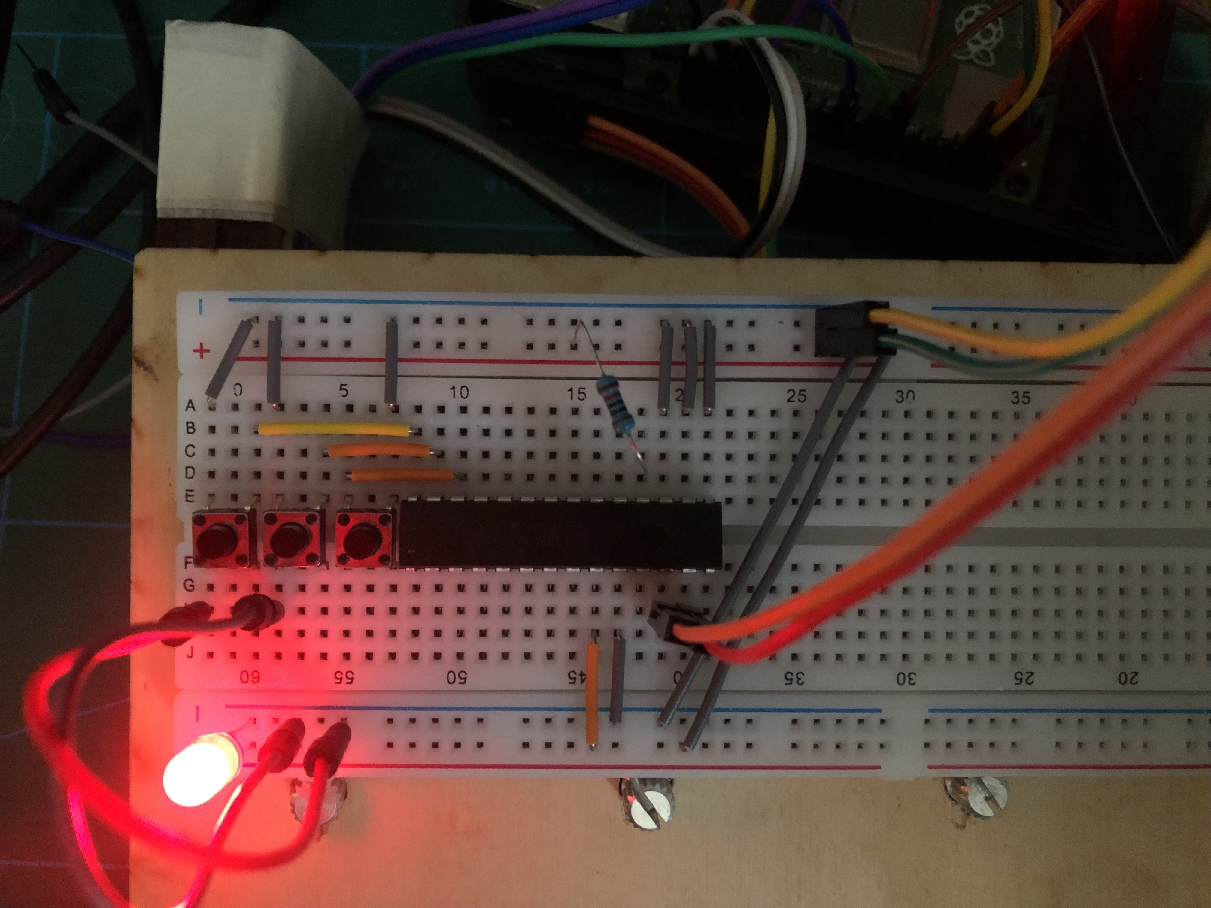
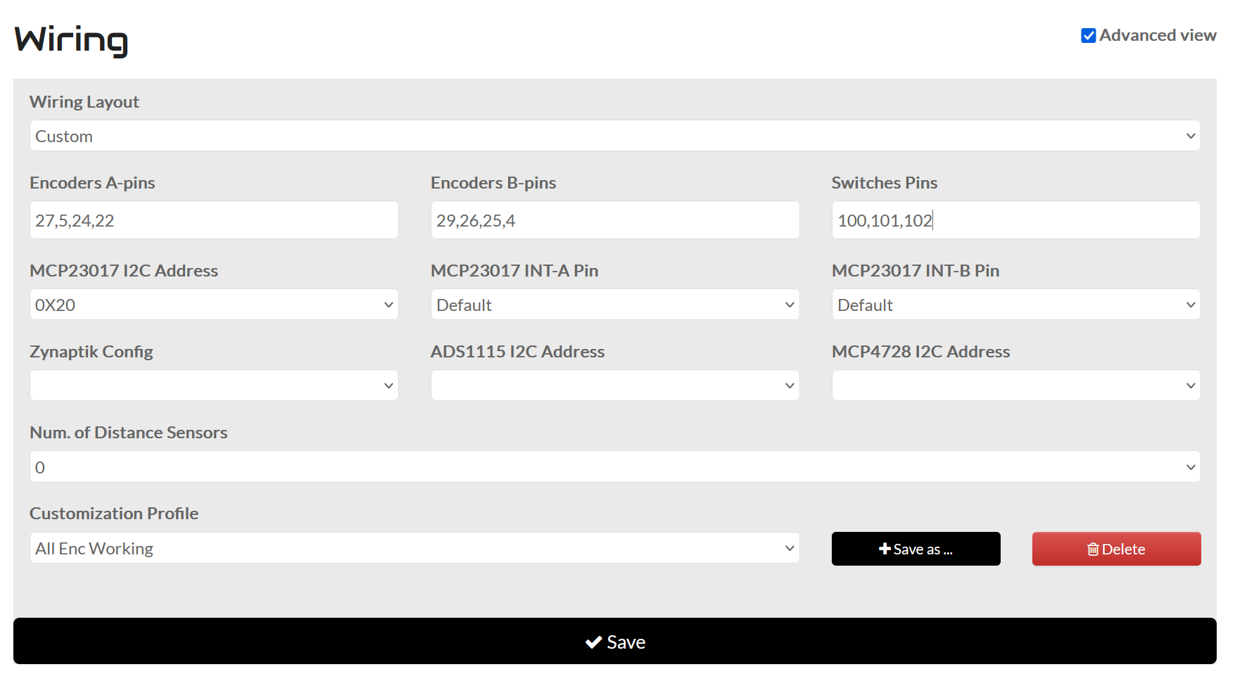
I’ve got an mcp23017 setup on the breadboard, my goal is to use these little buttons to test if they work better than the encoder buttons. I have managed to get the chip recognised by zynthian but it doesn’t want to register the button presses. I’m not sure if I’m wiring the buttons themselves incorrectly or if the numbers I’m using in the wiring page are incorrect.
The encoders are still wired directly to the gpio and have been working fine (the rotation part).
@stojos this is amazing, however for Latin American countries the manufacture of PCBs is extremely expensive and has high taxes.
I have access to CNC lasers that can manufacture these boards, but only on one side, would it be possible to evolve this project so that the boards have only one side?
I have no knowledge in PCB programming, hence the question.
Hi @francesconi , it is not possible to have pcb with only one copper layer because components are placed on both sides of PCB. There are switches and encoders on the top and everything else on the bottom.
You would need to separate components into two pcbs: one for switches and encoders and another for everything else and to introduce a connectors to connect these two pcbs. Probably you would also need to remove HUT from design and to differently rearrange switches so that they perfectly align to mcp23017 pins to avoid too many jumping wires.
I have designed one case long time ago and 3d printed it. It was designed for 4.3” screen and encoders on both sides. Assembly was too tedious with a lot of cables - hence me abandoning this approach and designing MINI. Miniature is good for putting zynthian into existing devices (e.g. into existing midi keyboards or midi pedals) but not great for standalone zynthian build where it is important to have exposed rpi’s usb, network and power connectors.
A wiki would be very welcome!
I saw that you use a stereo output for the audio.
Would it be possible to convert it into 2 mono outputs and when connected to the L side, all the audio would be mono only on L, like on musical keyboards?
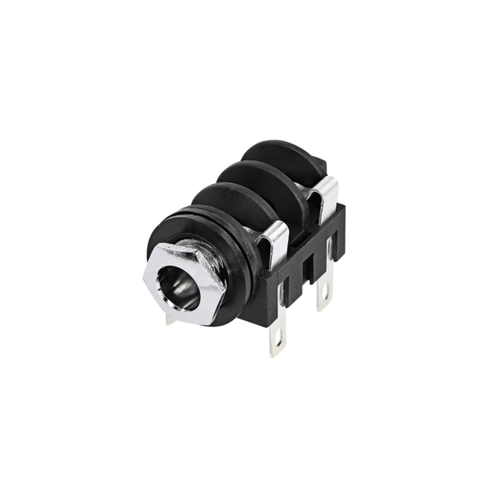
PCB design that I mentioned here come with simple connector for audio out left and right and ground. That means that if you want to use 1/4” jack (2 monos or a single stereo) you will need to buy panel connectors and solder wires from pcb connecter to jacks. If you want to have left jack to connect to both left and right channel when right jack is not connected you need readily available Neutrik NMJ4HC-S 1/4” panel connector like on image bellow and connect rear right pin of left jack to rear left pin of the right jack. If you look closely to jack you will see that this will short left to right channel when nothing is connected to right jack but also disconnect rear left pin of right jack when right jack is in use.