Many thanks,
I partially solved. The problem is the display pins. By connecting an HDMI monitor everything works except encoder A.
I did it!!! I moved some pins of the encoders, I remapped on Web conf and the display now works … !!!
Thank you very much everyone for the technical and moral support.
Time to print the container and I will post an audio file with sound…
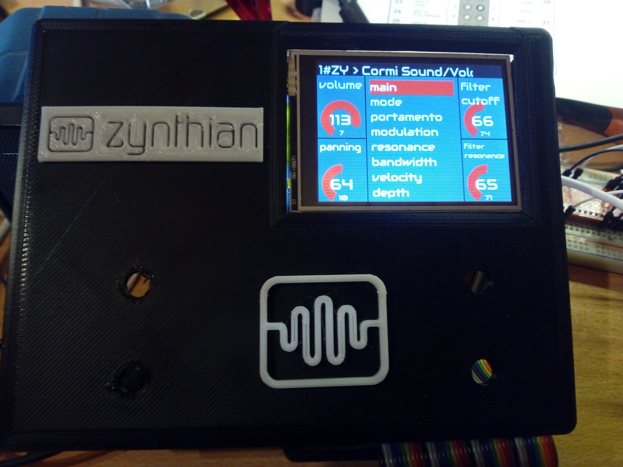
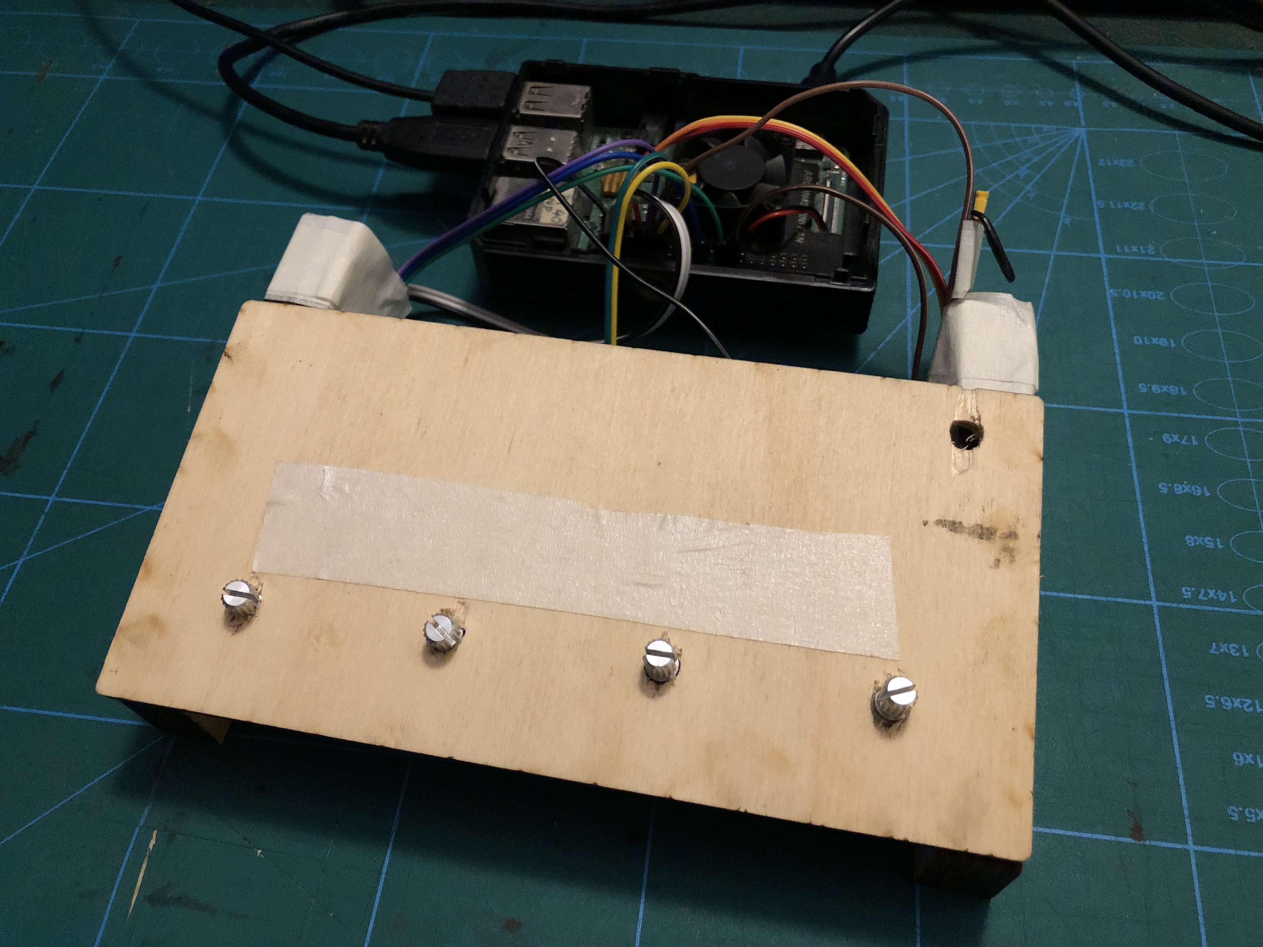
In the meantime, place the newly printed front panel …
2 Likes
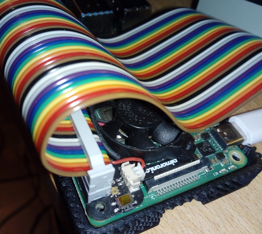
Has anyone tried to mount the Pimoroni fan?
Does it create noise?
Thanks
P.S.
It doesn’t seem to cause any noise…
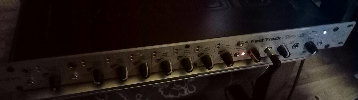
I connected Zynthian to an M-Audio fast track sound card that I could no longer use in the recording room as it is obsolete … and it works great. Great sounds. There is no need to change the sound card on the raspberry, because it automatically takes the place of the other … very well
Hi!
please help me, which pins should I use for direct connection of the encoders in this case?
Thanks in advance!
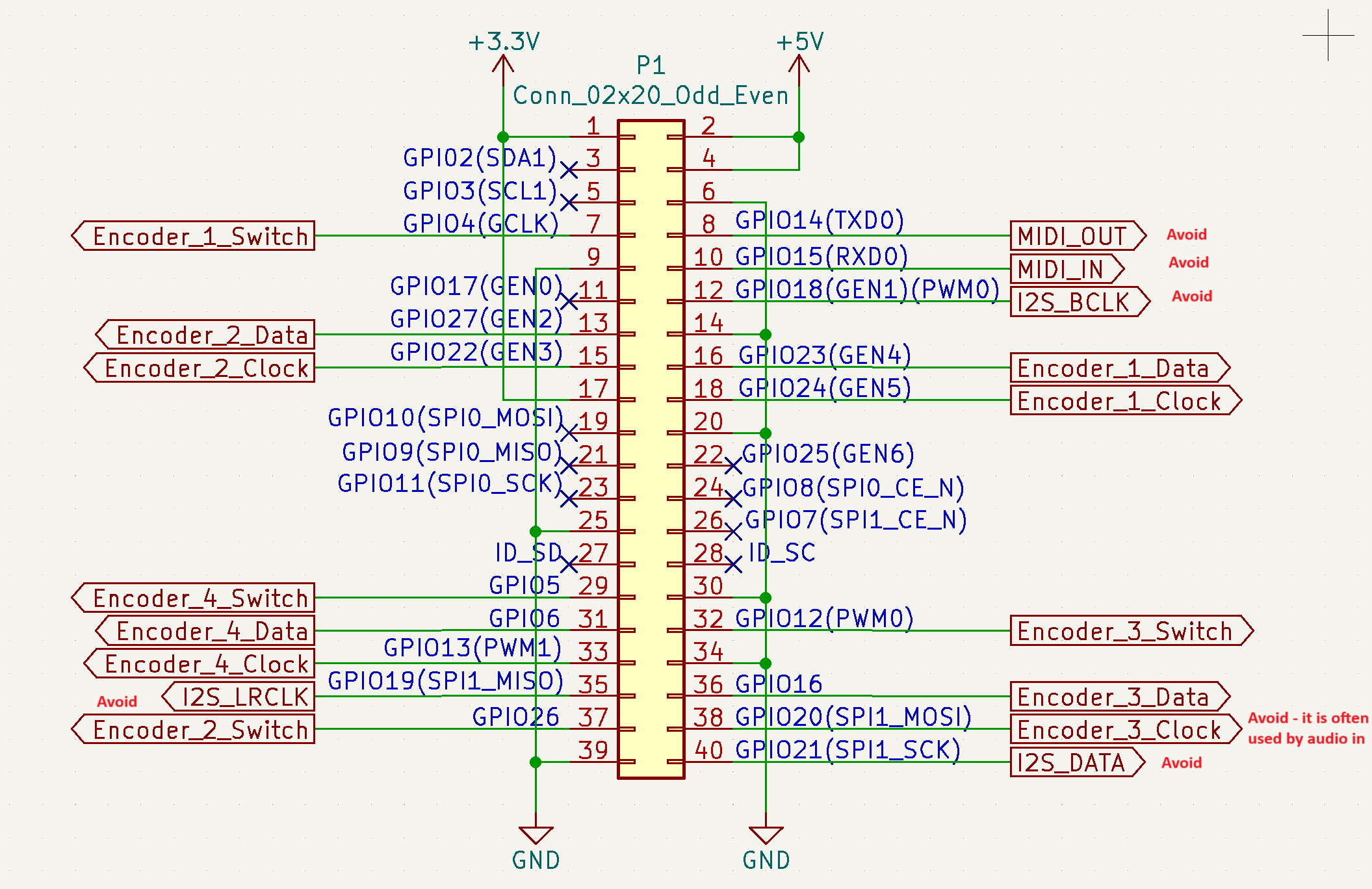
Hi @szatmarip. Do you plan to use an I2S DAC, a SPI display or hw MIDi ? They All use GPIOS. Otherwise à full Zynthian V4 use 16 GPIOS.
You need to avoid serial pins for midi, i2s pins and audio protocol and their in and out data pins (audio in data pin is only occupied if audio card has adc capability - only few have it).
If you use dsi screen you do not need to worry about pins occupied by screen.
Do not forget that you will need debouncing 100n capacitor for each encoder’s switch and 10n debouncing capacitor for each encoder A and B lines (two per encoder).
I have design before minimalistic zynthian rpi HUT that provides just MIDI IN/OUT, audio out with cheap i2s card and 4 connectors for encoders. Three is also MIDI Through here but only available through connector because there is no enough space to put all PCB mounted MIDI connectors on such a small HUT. Also audio and all MIDI do have connector pins if you want to connect panel connectors to it.
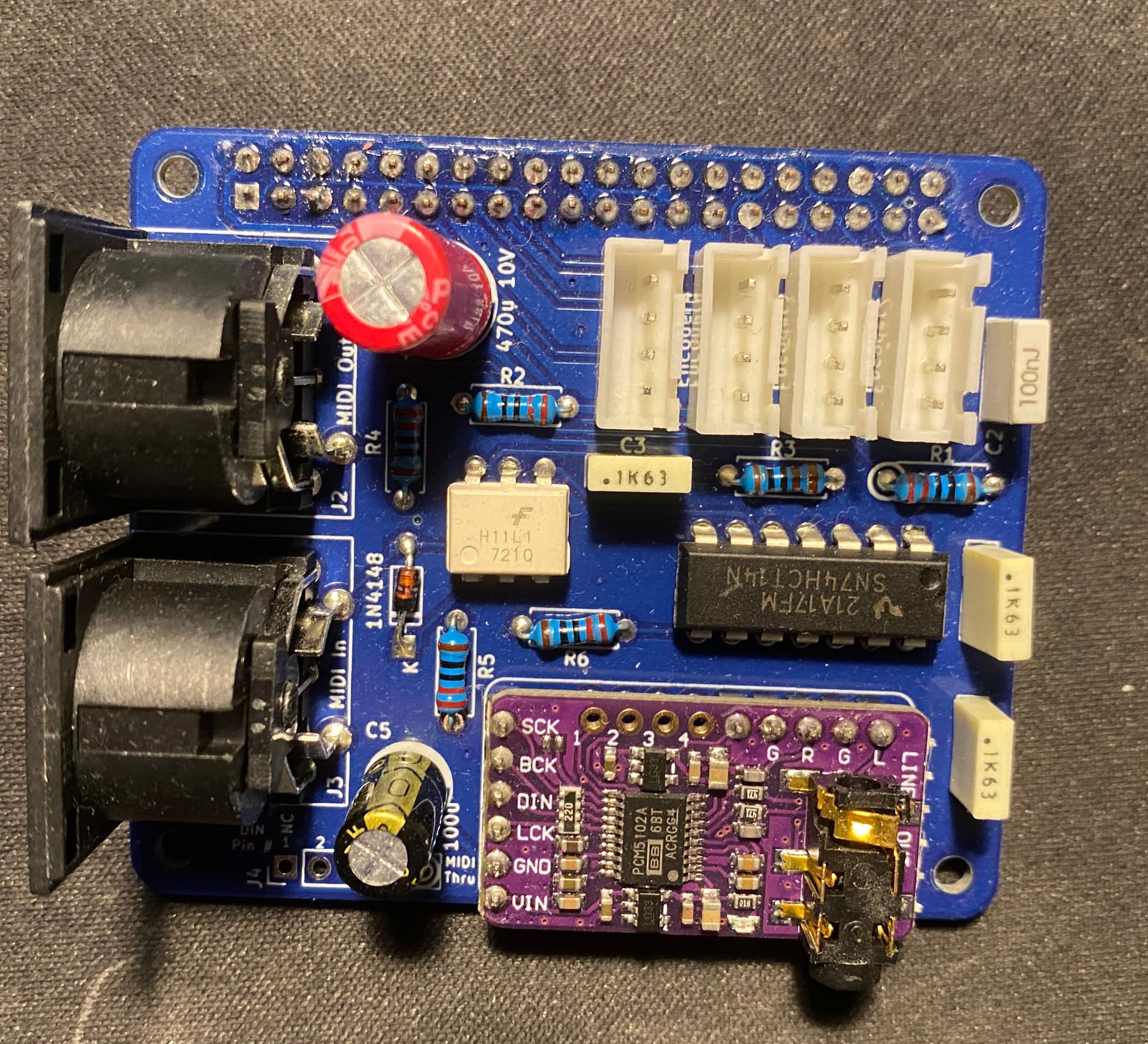
That minimalistic zynthian approach is doing what you want - connect encoders directly to rpi gpios. Here is the rpi connector from this schematics where you can see where encoders are connected.
If you are interested I have few PCB left from this old project. I can sell them to you for 10£ plus shipping. They also come with encoder PCBs where you need to solder capacitors . Here is how all 5 PCBs looks like.
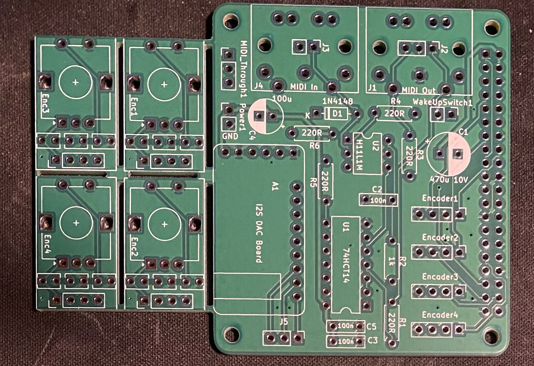
If you buy them I will send you bill of materials to assemble this (even though everything is labeled on PCB) .
If there is interest from other people I will create wiki page for all information about this very minimalistic zynthian hardware and share kicad project on zynthian-hw.
I have used this PCB on my zynthian pedal build explained here Pedal Board from Aeolus discussion
2 Likes
I have a touchscreen connected on GPIO, its a waweshare 5". Other than that there aren’t any other things on GPIO, sound is on an usb card and an usb midi keyboard is connected. I want to make this as minimalistic as possible, but the rotary encoders are a must.
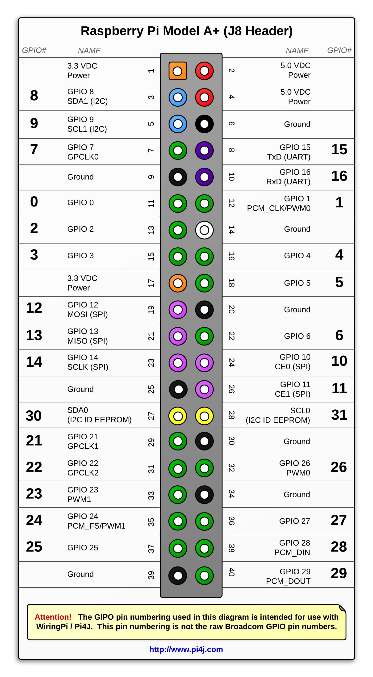
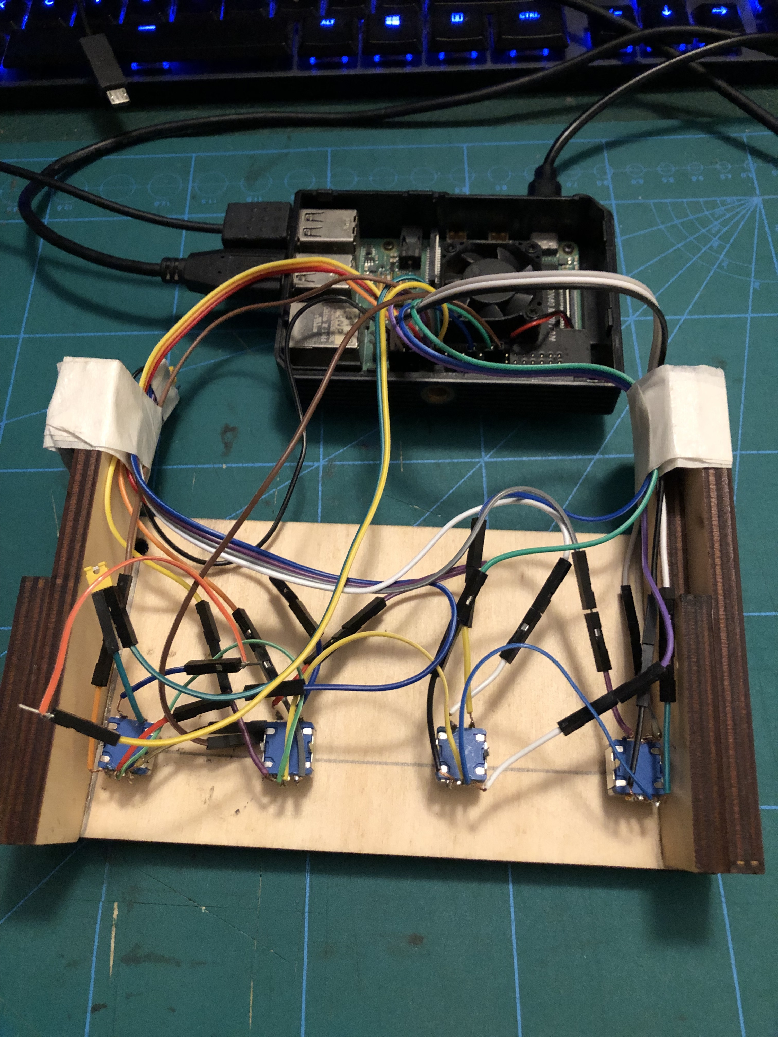
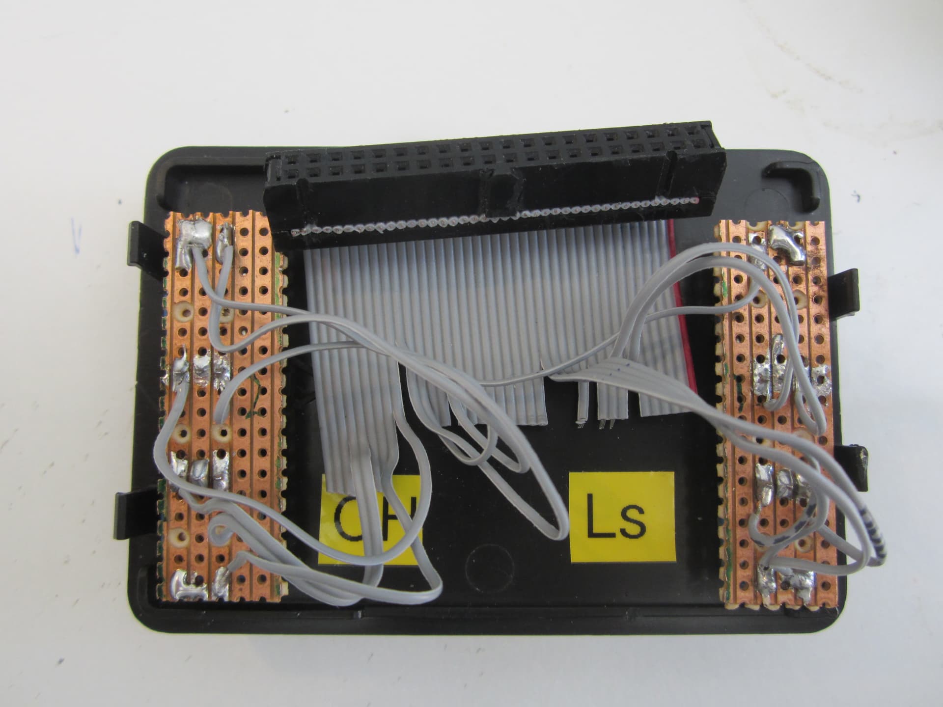
I made the connections myself following this image from another thread. I have a pi4 with usb audio. The wiring is a mess but I wanted to give it a try anyway before I laser cut a case and do it properly (this frame is scraps from laser cutting). I’ve been having the false button trigger problems as mentioned in this thread below. That was solved for this person by using the MCP23017 chip. I have a couple of these chips in the mail. I may make another slightly better (but temporary version) before I await @stojos to make a longer version of the zynthian mini PCB.
From a zynthian perspective if such a creed exists, your interface cut off is do you include Interface switches? That is the point at which GPIO interface were dropped because these were only officially ever implemented in 12c.
Here’s an implementation for devices like…
A minimal implementation.
It’s ultra minimal because it doesn’t look like you have capacitors. Does it work reliably for you on a current version of zynthian?
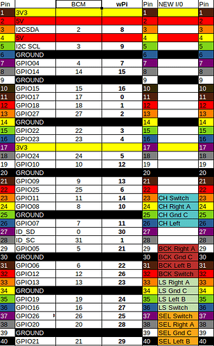
Btw, I’m not a fan of that pin diagram, I find it hard to follow when it’s not laid out like the physical connector.
It’s done many a thing reliably in the past. I haven’t loaded v5 to it, or rather I did but it was a pre oram test so it’s unlikely to have much creedance nowadays.
Your issue as you enter these territories is as you become more bespoke the more you can arrange a system that has a limited access which can reach almost humourous levels as you desperately try to reload a wifi hotspot when your internet connection is the only way to a file you happen to have on another device… but that’s the fun of doing stuff with bleeding edge code.
With your encoder layout will you chose a v4 or v5 style implementation?
I once moved from an organisation that did all it’s system diagrams on Autocad to one that stored it all in excel spread sheets. The drawings conveyed more information.
The chart developed out of precisely the complexities GPIO provides in that you have two different coding paradigm’s at work and to extend across the complexities of BCIM, GPIO and the Pi this was the best way to convey the information. as that sort of stuff works (to my mind) best in a chart. The colour hopefully indicates functionality as far as the individual encoders goes, one does what one can when addressing communities over personal record keeping.
But the joy is the different contexts we apply to similar problems and the result which is so often far greater than the some of the parts . . .
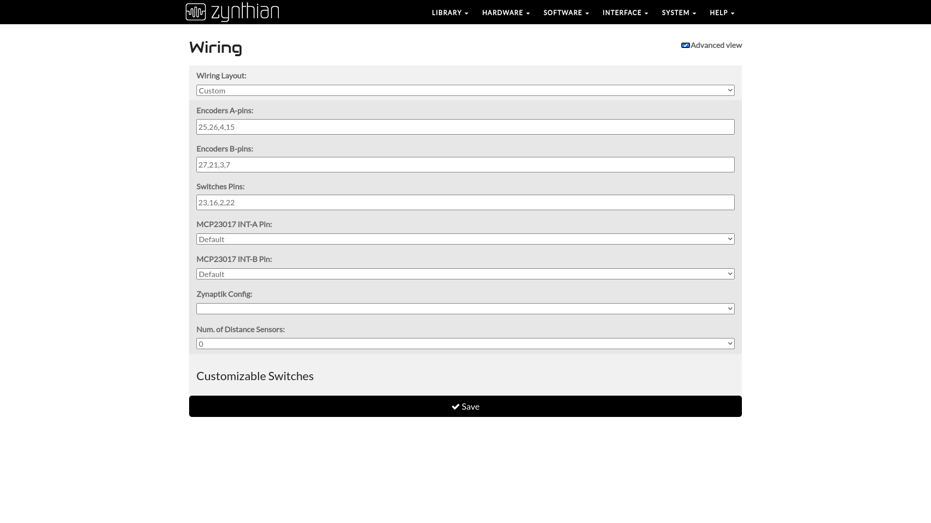
I set the buttons up like V4, I don’t quite understand how to configure the wiring screen (that is, I just choose ‘dummies’ and put the GPIO numbers in). But I may have to figure it out once I put the case together with the extra buttons and MCP chips and a V5 config becomes more viable.
Regarding the diagram, I ended up re-drawing it myself by hand with pins, wire colours and numbers to make it easier to reference for my specific setup.
Pretty much… Except the numbers in the pin descriptions are NOT the Pi pins .
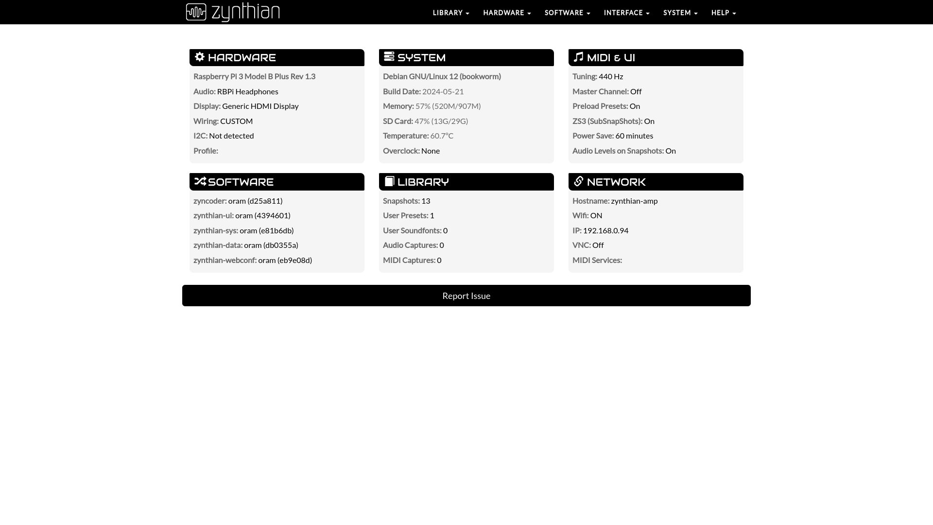
I’ll define it in a table and examine the zynthian-amp device to get a canonical statement for that particular implementation.
Well I’ve just opened up zynthian-amp.local and it started up perfectly, except the select encoder. The switch worked but the encoder didn’t . . .
A little visual inspection revealed one the wires going to the select encoder had disconnected. It’s ALWAYS the select encoder that mucks you about. . . But when dealing with GPIO Pi pin interfaces you can hunt this sort of problem back and forward between software and hardware . . . .
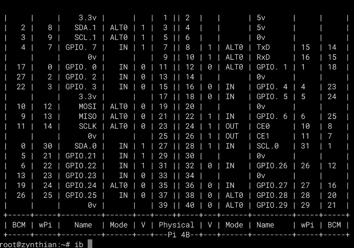
So that’s fixed. And the encoder mapping is …
| Pin on Pi connector | Number to stick into Webconf device | Details |
|---|---|---|
| 1 | - | 3.3V |
| 2 | - | 5V |
| 3 | 8 | 12C SDA |
| 4 | - | 5V |
| 5 | 9 | 12C SLA |
| 6 | - | Ground |
| 7 | 7 | Select Encoder B Pin |
| 8 | 15 | Select Encoder A Pin |
| 9 | - | Ground |
| 10 | 16 | Back Encoder Switch |
| 11 | 0 | - |
| 12 | 1 | - |
| 13 | 2 | LS Encoder Switch |
| 14 | - | Ground |
| 15 | 3 | LS Encoder B Pin |
| 16 | 4 | LS Encoder A Pin |
| 17 | - | 3.3V |
| 18 | 5 | - |
| 19 | 12 | - |
| 20 | - | Ground |
| 21 | 13 | - |
| 22 | 6 | - |
| 23 | 14 | - |
| 24 | 10 | - |
| 25 | - | Ground |
| 26 | 11 | - |
| 27 | 30 | - |
| 28 | 1 | - |
| 29 | 21 | Back Encoder B Pin |
| 30 | - | Ground |
| 31 | 22 | Select Encoder Switch |
| 32 | 26 | Back Encoder A Pin |
| 33 | 23 | CH Encoder Switch |
| 34 | - | Ground |
| 35 | 24 | - |
| 36 | 27 | Ch Encoder B Pin |
| 37 | 25 | Ch Encoder A Pin |
| 38 | 28 | - |
| 39 | - | Ground |
| 40 | 29 | - |
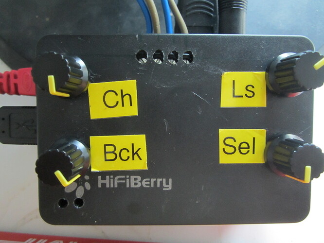
So the ordering of the Encoders in the Webconf is
Ch, Back, Ls, Select…
So above is the overall table of mappings of GPIO pin to number in the webconf
To reduce it to just the working implementation for my V3 machine it reduces to…
| Device | GPIO Pin connected to | Value in Webconf |
|---|---|---|
| Ch encoder A | 37 | 25 |
| Ch encoder B | 36 | 27 |
| Ch Switch | 33 | 23 |
| Back encoder A | 32 | 26 |
| Back encoder B | 29 | 21 |
| Back Switch | 10 | 16 |
| Ls encoder A | 16 | 4 |
| Ls encoder B | 15 | 3 |
| Ls Switch | 13 | 2 |
| Select encoder A | 8 | 15 |
| Select encoder B | 7 | 7 |
| Select Switch | 31 | 22 |
Which matches up with the Webconf values !!!
Sorry it’s a table but it does at least completely define a working ( v3) solution. I’d probably add the caps but I doubt I could squeeze it all into the case.
I feel honour bound to repeat this. The colourful table defines another working combination when it was last written but I wouldn’t vouch for it now. There are at least two wires resoldered on this particular board which was done simply because it suddenly stopped working and after exhausting hardware checking revealed itself to be a low level alteration in the Pi code which required a new pin to be chosen. Quite if a V5 Pi ( yes it does get confusing…) will behave nicely is a different point. They are sacrificing dragons down there I hear . . .
1 Like
The capacitors filter switch bounce which can be filtered programatically (and indeed is) but the way we interface via MCP23017 chips means that each bounce triggers an interrupt and steals CPU cycles that are far better targetted at our core purpose of making sweet music. Direct interfacing to pins or using some other intermediary (like an MCU that does the debouncing itself) can remove the need for filter capactiors. I have long been an advocate for replacking the MCP23017 with a microcontroller but during a recent discussion this idea was roundly rejected on the rather pragmatic basis of, “It ain’t broke”!
3 Likes
Well that’s good news !
I’ve just put a clean oram on the zynthian-amp above and it accepts it!!!
And the encoders work!
Not had it doing anything audio yet but I’ll rig it up to see how it behaves . . .
1 Like
Interesting fact that I discovered is that encoder denouncing capacitors are more important when encoders are connected through gpio extender than when encoders are connected directly to rpi pins. Encoders directly connected to rpi pins never failed to work for me even when there was no debouncing caps. However they fail to work after few turns when they are connected through gpio extender and without debouncing caps.
Regarding the MCP23017 and debouncing capacitors. As i explained some weeks ago:
There is a known issue in the mcp23017. This issue has caused that MicroChip change the specification (not the design!!), reducing the number of input pins. The issue cause the chip to malfunction and must be resetted. In my experience, the issue is mitigated largely by using debouncing capacitors, reducing the number of switches and interrupts generated.
Regards,
1 Like
I have found for my setup above, the rotation is accepted happily and quite reliably. The button presses not so much. I seem to be unable to do any kind of (intentional) bold or long press. Any time I try and use the select button it sort of works then the ghost presses start which always take me to the shutdown screen(similar to those people in the thread I linked).
Getting the wiring correct was a bit off trial and error. I got to a point where I had it half right, then I would cut and paste the whole collection of numbers from switch B to button field in webconf. The button pin on these encoders might not be where I think it is. It’s all assigned correctly now anyway, just stuck with problems mentioned.
Seems generally ok on mine, but it’s not quite right.
I’ve given it a fair bit of exercise and I don’t notice problems. Might be worth trying caps on the switches to de-bounce them a little. I would use a scope to watch the switch and see how much bounce there actually is on the switch.
There does seem to be a press event trigger on the select encoder from the briefest of initial touch…
Audio File Player seems rather incoherent.
My MCP23017 equipped zynthian-rack5 ( an early zynaptik) seems ok…
Ah, I missed this. Now it is clear. Thanks.