I had seen this controller… does it have motorized sliders?
Not at all, but feel free to change the code ![]()
For motorized, go to MidiBox
1 Like
Notes & volts is a really a good chain for learning midi basics (HW & SW sides).
As a good radio amateur, first I try to build with my hands… Putting a display is not a big problem… now I’ll test my machine and then I’ll think about it… For now I’ve saved money by printing in PLA, if then I will make changes and everything will be finished, then I will print in ABS.
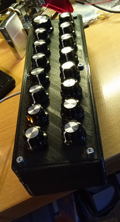
Obviously to connect the 16 potentiometers to the Arduino Pro Micro, I used a multiplexer.

2 Likes
I’d like to insert an Oled display that tells me what I’m touching and the value of the potentiometer I move… if anyone wants to give me help… I’d be happy… ![]()
These small ssd1306 OLED displays are pretty easy do use. They communicate via the I2C protocol, so just 2 wires (plus supply voltage and GND). There is a good Adafruit SSD1306 Library which (together with the general Adafruit Graphics Library) takes away the nitty-gritty and you can find plenty tutorials on the net how to use them. If you want to share your current code, we could tell you where to put the display update calls and what data to use.
1 Like
Thanks mbvs,
I have already used those displays always successfully… but in this case I didn’t make the sketch and therefore I don’t know enough about it to get my hands on it without putting my eyes on it… I attach the sketch which is exactly what I used for the MiniMoog controller and which I downloaded from the internet (in fact it also includes buttons which in this case are not there).
Thank you again
ControllerSAx.ino (20.8 KB)
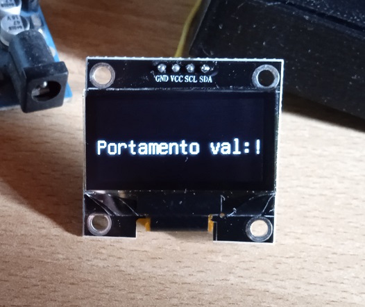
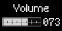
In practice something like this… When you move a potentiometer, the message appears showing what that potentiometer modifies and the value…
So, given you got the the display wired and the libs to drive it installed (which, if I understand you correctly, you are comfortable with) insert your code to output the values starting at line 563, right after the debug output (which you can take some hints from).
This code runs in a loop with i storing the current pot:
MIDI_CH contains the MIDI Channel as configured in line 178
POT_CC_N[i] contains the current CC number as configured in line 124 (if you want strings instead of CC numbers you would need to configure your own lookUp table)
potMidiCState[i] contains the current value for this CC
potMidiPState[i] contains the previous value for this CC
The code at this point should only run for pots which are currently changing, so no need to compare the previous state with the current state. Still, when you turn two pots at the same time they would overwrite each other. And the last change stays in the display for ever …
NB: nothing tested, written just out of the blue - if you get stuck, let me know, I think I can cobble something together on a breadboard and do it properly ![]()
Thank you very much for your help.
I’ll try it tomorrow and let you know how it goes.
Thank you
you’re welcome - thank you for the oppertunity!
This is beautiful… I’m an old Radio Amateur and until a few years ago the Ham-Spirit existed, the desire to help those who know less than us. Through my site (iz3zlu.weebly.com) I have done it 1000 times… it is certainly something that makes you feel very good.
HI mbvs,
I’ve been banging my head around it since this morning but I keep getting errors… I’ve used these displays with very small sketches (keyers, V-Meters and more…) but here I have a sketch that’s too complicated for me to get my hands on. … I also tried to lighten it by removing the entries regarding the buttons but I can’t… If you have the time and desire… without rushing to put it together, you would give me a gift and I would learn something… all I need is the code for a potentiometer… then I’ll put the others with their names… Thanks in any case for your interest and help…
No problem, give me a day or two and we’ll see what I can come up with.
1 Like
Very kind… Thank you. No rush… I’m waiting for an Arduino Pro Micro and I had to rearrange the display that I broke…
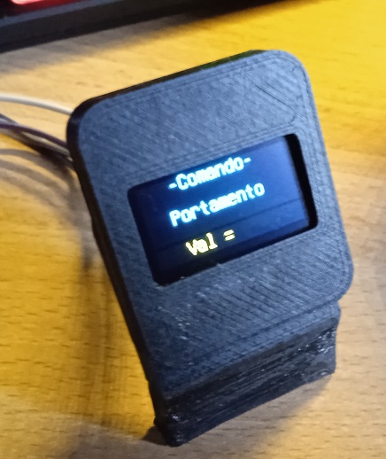
Oled display connected and working… now I have to understand how to send the values of the various potentiometers…
1 Like
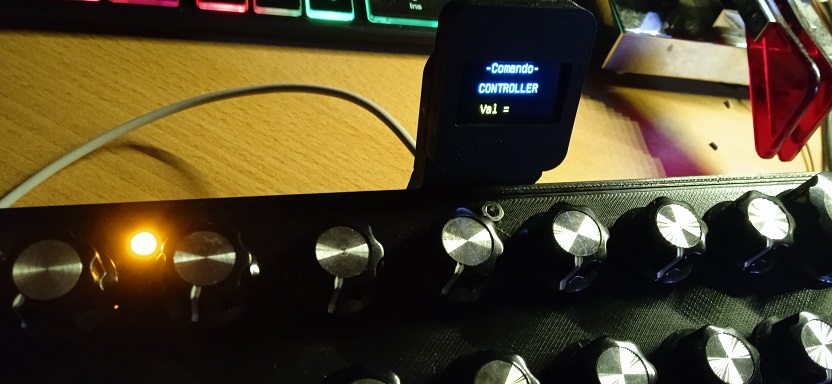
… working on it:
can you tell me which controller your display has? Is it one of the smaller ones with an SSD1306 or one of the bigger ones with an SH1106?
2 Likes
WONDERFUL!!! Many thanks.
U8GLIB_SSD1306_128X64 u8g(U8G_I2C_OPT_NONE|U8G_I2C_OPT_DEV_0); // I2C / TWI
This is the U8GLIB library string that makes my Oled display work.
Great work…thank you
Will you tell me if I can also thank you on the site you attached…
And this is the sketch I started editing:
ControllerSAxDisplay.ino (21.8 KB)
@mbvs
You could make sure that there is a CLEAR after a few seconds that the writing appears… There is no need to constantly have the writing on the display. In this way, if you touch two potentiometers and the writing freezes, after a few seconds the display clears… I have some ideas but I don’t know how to write them on the sketch… I apologize
2 Likes
yepp, already implemented - I probably overdo this a bit (just have implemented optional 2 line cc mapping strings) but it is coming along. RL is keeping me on my toes, so give me some more days …
Don’t worry. You are also too kind. Take your time.
Thanks