As @robert, I find these USB interfaces very handy.
First of all they mostly all work out of the box.
They are convinient: I use mine with its two combo XLR/jack plug, built in preamp whenever I want to plug a guitar, a bass or a dynamic microphone.
[edit] and quiet cheap [/edit]
Imho, the main reason for Zynthian Team to stick to a simple input stage is that everyone setup/use case/needs is different.
Yes I understand that we should not base our strategy on old products from eBay. I just wanted to inform people that it is possible option while there are still few available for reasonable price.
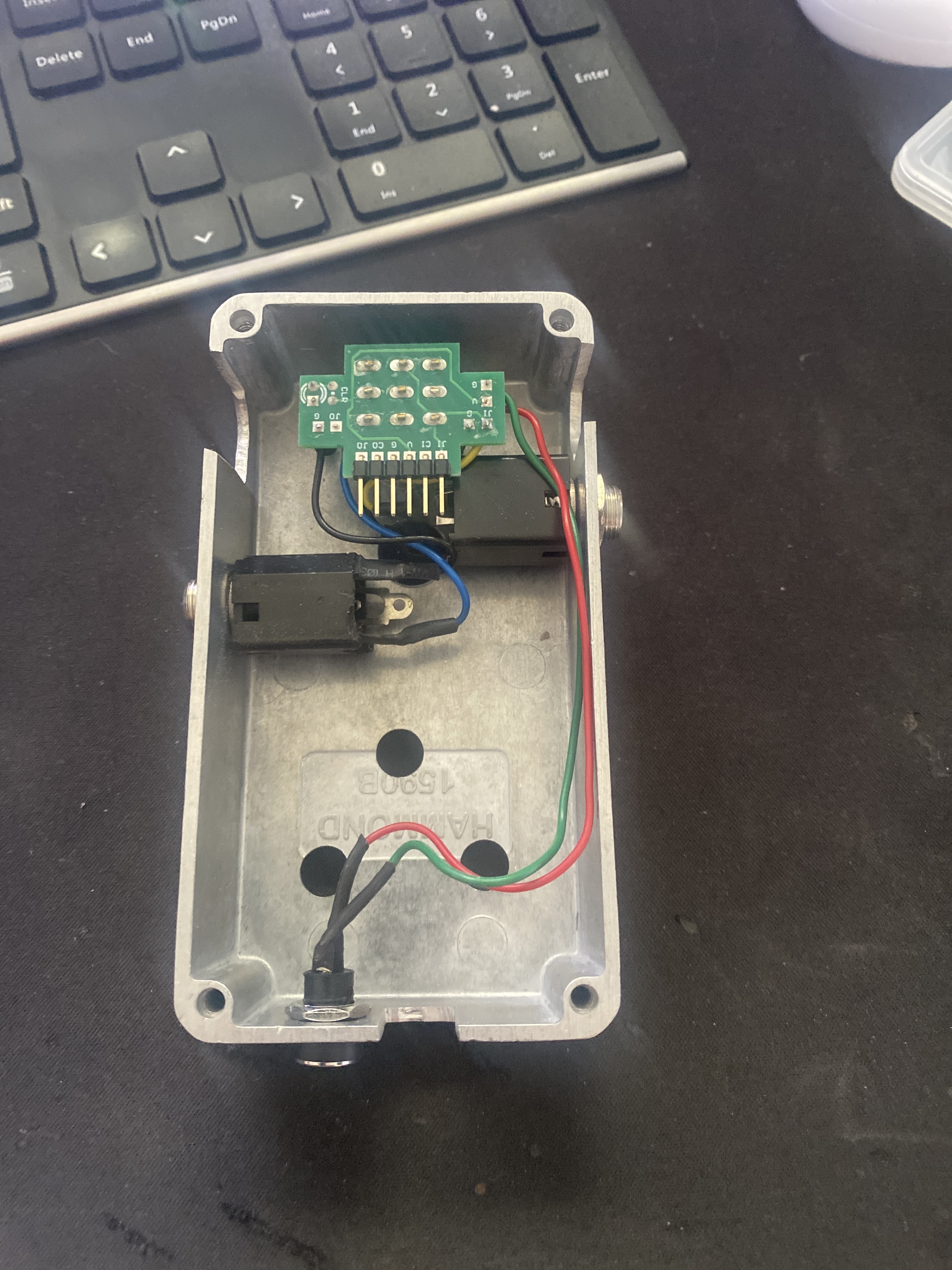
Another two options that I listed both require 9V power, in and out jacks and case. Luckily I have a diy pedal that has all that and can easily accommodate PCB so that I can quickly test if these simple schematics are any good.
1 Like
Perhaps the PCB could have the necessary traces for the guitar input buffer, and bypass traces as well, so you would “cut here” and populate the parts to get the optional guitar feature. The option could be offered by Zynthian Labs or DIY.
Indeed, the implementation isn’t really the challenge. Any such work requires substantial effort in design, test, iteration. Unless there is sufficient benefit to the designers, it won’t happen. This is not likely to invoke a desire in @jofemodo - he’s not a guitarist. It is only likely to happen if there were a lot of desire from a lot of potential customers. I love the idea but I’m just one person and there are relatively cheap and easy solutions externally as previously described. Yes, it would be wonderful to add this functionality but it seems unlikely to happen. We can still hope and pray but that seldom conjures miracles!
Do check out the Mod Dwarf which is dedicated as a guitar effect with appropriate hardware.
1 Like
How would you switch the buffer circuit? A physical switch is not an option. It must be a switch controlled by software. Solid state relays?
I could consider adding this circuit to the V5.x main board if somebody else design and test the circuit, including the switching part and the BOM, so I can simply drop it into the scheme, place the components and route. In such a case, a single prototype could be enough. Not for next version, v5.1, but it could be added for v5.2.
Regards
3 Likes
I remembered there used to be something called PedalPi, which was a little Pi-hat for the zero, and they used this microchip for the amplification stage:
PedalPi used an opamp (which many dislike due to odd frequency and phase response) with an input impedance of 500K (0.5M). The minimum input impedance recommended for a guitar is 1M (which Boss pedals offer), preferably higher. An old valve amp would likely have an input impedance of 10M. Zynthian has an input impedance of 20K which is 1/50 of the minimum recommendation for guitar.
@jofemodo I will have a think about how we might design and test such an addition. It may be that we do as @tunagenes suggests and offer the ability for the user to modify with tracks available on the PCB to facilitate additional / alternative components… but I would prefer it be part of the core design. As you say, this is not going to happen soon but we can aspire to greatness!
1 Like
The impedance of the instrument inputs is 1 MΩ in the Behringer UMC interfaces. I use an UMC202HD as guitar/bass buffer and microphone preamp before the input of the HiFiBerry DAC+ ADC.
1 Like
Sorry! I read that UMC1820 had lower impedance but I now see that switched to instrument input it has 1M input impedance. I will revisit it as my guitar interface. It is already planned as my portable, multiport zynthian rig where I would be mostly using the guitar.
I don’t see a reason because a good opamp couldn’t do the task perfectly. Indeed, better than a simple JFET circuit. Perhaps this “dislike” is due to the “color” added by the JFET, I mean, if you are used to JFET buffers, your ears will feel the opamp signal as odd because it’s flatter, without any extra color added. In this case, we should think if we really want the input buffer adds some color or let the signal to enter as pure as possible, letting the zynthian add the desired color. This is just my first thoughts. I don’t have any experience with guitar pedals so perhaps i’m totally wrong.
Regards,
1 Like
The theory is that the very high gain of an opamp requires negative feedback to control it which leads to frequency dependent phase errors and odd sounds. Of course you could be right that guitarists who prefer jfets also prefer valves (tubes) that have similar characteristics.
Anyway, although the JFET input stage could be a very simple circuit, there are challenges including:
- JFET are increasingly difficult to find with many manufacturers stopping production
- JFET are inconsistent with very different characteristics from one unit to the next, even from the same batch
These issues would likely make it impractical to add a JFET based input stage. We wouldn’t want to be tweaking components for each device built.
I would prefer the audio capture is transparent without colouring the signal significantly then using effects to apply the sound scaping. So maybe Opamp input stages could be a better choice but that comes with its own challenges, particularly around noise and oscillation.
1 Like
Input stages are subject of continuous discussions in dedicated forums. As @jofemodo says, some prefer the JFET warm sound while others needs flat response.
I’m using my UMC 204 with a guitar/bass and a dynamic mic. Two kind of signals, but the audio interface and its built in preamp make it well.
But, yes, sound is dry. IMO, it’s Zynthian job to enhance it.
My suggestion is to let the more motivated use the input stage they wants. By placing mechanical mount points and 0.1" headers on the base board:
- between ADC and existing filter, with the fully differential inputs exposed
- between filter and audio jack (so that existing filter can be by passed or not. + Some solder pads for audio signal path routing)
- power. Vin from barrel jack (for Opamp, transistors), 5V, GND
- why not signals like I2C, GPIO. One can imagine the use of programmable chip (resistor for gain control, mute/unmute ompamp …)
There’s room on the base board and enough space between the two Zynthian’s boards.
And this solution will add close to zero cost !
1 Like
I think that’s a great idea. And if a particular design proves good and popular enough it could be ‘flattened’ on to the main-board!
Over on the Daisy forum an open source-hardware pedal kit has been announced which may provide some good circuits and info on specific capacitor types to use, etc:
1 Like
That’s quite interesting. A neat kit to package up a microcontroller into a foot pedal. I can see some potential flaws in their audio path design. The input impedance is about 0.3M and the voltage follower opamp may need some stabilisation. The NE5532 dual opamp chip was my choice about 30 years ago but I might choose something else these days.
I think they missed a trick not feeding both channels of audio, at least on the output to allow stereo/ widening effects.
I’ve been researching JFET & opamp high input impedance “buffers” and the opamp is probably the more appropriate solution for us. It can be consistently built with no AOT process and good (enough) quality opamps are fairly cheap now.
[Edit] I have posted my critical (but I hope supportive) feedback on the linked forum.
2 Likes
Another Pedal kit based on Daisy Seed is Terrarium:
The schematic is on page 3:
I would probably go for a MCP6022 opamp. Its performance is pretty good and crucially, it supports rail-to-rail output which, when running from single 5V rail, is pretty important. Almost all other common opamps only get within a volt of each rail. The MCP6022 only has a max. supply of 5.5V but if using in a 5V environment it looks the most suitable candidate. The noise, distortion, etc. look acceptable (expecially for guitar). I don’t have any in my toolkit but might order some to test some circuit designs. It should make a good voltage follower with >1MΩ input impedance and with the right circuit, it could have switchable input impedance. I wonder if we could do something with the multiplex input to the Zynthian - but extra input connectors may prove challenging to accommodate.
I have got pcb and ordered opamp TL072 to assemble this schematics for investigation purposes.
Is this schematics worth the effort?
1 Like
The TL072 is a very popular opamp used for guitar preamps. It isn’t very hi-fi, with average noise and distortion but these are fine for a guitar amp and, because it is so commonly used, its performance may seem familiar. It does support a wide supply voltage range including 0-5V (unlike NE5532 whose datasheet says its minimum voltage is +/- 5V). It doesn’t have rail-to-rail output but gets quite close (I think within 0.2V of each rail) which means it will clip less easily with a hot input.
The circuit looks about right. The opamp is configured as a voltage follower so giving unit gain. I think the TL072 may be less stable than some others so might require some extra components to tame it - you can find out… (The NE5532 can do unity gain but some other opamps are unstable, requiring higher gain or external compensation capacitors. I think that the TL072 may be unstable with unity gain if the input gets too hot which might be an issue with low supply voltage.) C2 acts as a d.c. blocking capacitor, decoupling the source (guitar pickups) from the d.c. offset of the opamp input (virtual ground). R1 & R2 act as a potential divider to provide the d.c. bias or virutal earth at 2.5V above ground (assuming you power from 5V). C1 forms a low-pass filter to smooth this virtual earth, decoupling ripple in the supply rails or induced through R1 due to circuit load. R3 decouples the potential divider and particularly C1 smoothing capacitor from the input. We don’t want this filtering the audio, just the supply. C3 & R5 form a high-pass filter, removing the d.c. offset present at the output of the opamp. R5 may not be required because the output will be connected to something that we expect to be relatively low impedance (compared with this buffer’s input impedance), e.g. 10K. R4 helps to protect the output against short circuit. It may not be required if this is permanently connected to the next stage. The supply voltage is not indicated and there are extras like protection diode and PSU indication LED.
This is pretty similar to the circuit I am currently working on. Mine uses the MCP6022. I was simulating it online but ran out of license time and my local installation of kicad is broken. I will try to get it into a simulator and play with values to check out frequence and phase response and also what happens with noise, etc.
The TL072 has a JFET input. Watch out for an effect where the gate exceeds limits and it locks up until the signal has drifted back to (apparent) zero. It will manifest as the signal disappearing or becoming extremely distorted and possibly low level until silence has been received for some time. Depending on the time constant of the trigger, this could be a few seconds or it could be very short, giving a motorboating effect. (Some say it sounds like farting.) This could indicate that the input is too hot (loud) for the TL072 and could require significant changes or maybe just a different Opamp.
[Edit] With C1=47uF it will take about 8 seconds to settle. I wonder if a smaller value will still work, e.g. 4.7uF which will stablise in about a second.
4 Likes
It is supposed to work with 9V supply voltage and additional led and required resistor are used when this buffer is put inside the pedal.
I have ordered dc 5v to 9v usb cable converter so that i can test this by plugging into 5v USB on zynthian.
Idea is to fit this a small pcb into a small 3d printed box and plug it into zynthian audio in and USB when guitar is in use.
1 Like