Is there somebody who knows how to connect a IO Pi Plus board to Zynthian.
and with what wiring configuration. I can’t figure out how to het it to work.
If I type i2cdetect -y 1 in the terminal I can see that on adress 20 and 21 the 2307 are found.
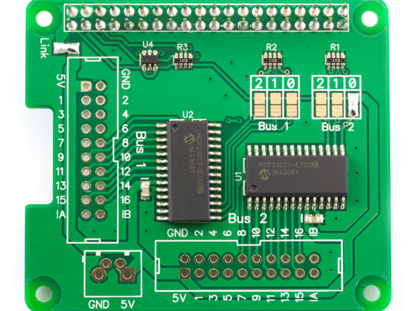
I would expect that if in the I choose V5 in the wiring config and hookup the INTA and B (of thr IO plus) to the corresponding pins (29,31 traced back on the PCB layout of the Zynthian mainboard)
Things should be working. but there is no raction on any pin of the board.
This board? hook up the i2c wires to the correct pins on the pi. (3 and 5}. And psu (+5v pin 2 or 4) and gnd You should then be able to run i2c_detect -y 1 and see if the chips are detected.
I’m still documenting encoder connection so this probably develop into the mc23017 section of the wiki…
I was expecting you to answer, as the pin-out wizard
I checked in the terminal and I can see that adress 20 and 21 are detected.
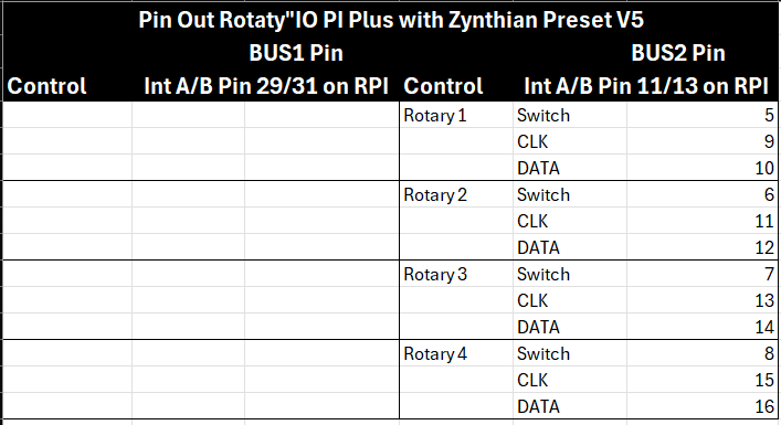
Since this is a kind of the same setup as the original controlboard. I have traced back the connections and found that int 1 and 2 are on pin 29,31 of the PI and int 3 and 4 are on pin 11,13 of the PI. So I connected these to the int pins on the IO Plus.
I would expect that if I select the V5 wiring preset that the rotaty’s should be working thru the IP Plus but there is no reaction on any of the pins. Which is a bit weird.
I found out that I wasn’t thinking wrong. But from all the rotary’s I have lying around I picked a broken one to test . I can get the Rotary’s to work when I hook them up the same as they are on the control board and connect the INT correctly (as on the controlboard) and load the V5 preset in the config.
With good wiring it works like a charm now.
Just in the pub after a bracing (totally knackering) walk round Tatton park. Everybody is busy reviewing pictures so I’ve got my phone out more news as we get it.
Which leaves two essential issues to address Firstly,
But far more importantly,
What are you going to do with the second 23017…?
Are you about to do your own zynaptik to process switches and LED’s or are you going to add more encoders?
You’ll get a lot less rook soup if you say encoders and you’ll be drowning in the stuff if you say nothing!
You can tell I’m stiff and grumpy from the walk and the fact I didn’t read the thread properly , so
I had all the suff lying around and used it for testing if this was something to go on with.
But since I’m pretty lazy , I think I just order the Control board and use this, solves al the problems. I already traced the contacts so it should not be difficult to use this without the mainboard.