I2C lit encoders

Look what’s just turned up from Italy…

It’s those very sexy rgb lit encoders with 12c connections…

6 Likes

NO WAY!!! :frowning: What I should do now with my dumb unlighted encoders?? >>>>>>>>>>>>>>>>>>>>>

JK, JK, :slight_smile: but anyway that an AWESOME idea to have lighted encoders, then you may be relieved from sometimes guesswork on it’s position…

2 Likes

I think you might be slightly misunderstanding the implementation.
The knob displays a colour but does not display an encoder position. There is an example that got built as an experiment . Zynthian MIDI-UB Controller

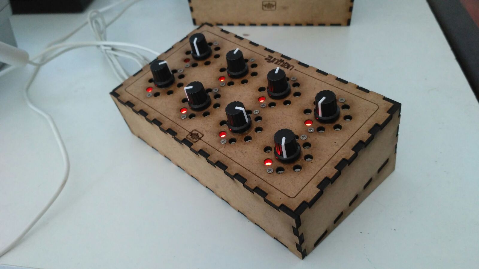
It also demonstrates the difficulty of lining up lights and encoder pointers !!

But what I’m working with are encoders that have one settable colour. Now there are few things we can do.
1/ Set the colour of four knobs to match the GUI display colour.
This would give a strong conformity of look.
2/ Set the colours in the GUI to match colours individually displayed by the knobs. Very strong linking that would make the Interface more intuitive. ( Might also end up looking ghastly… I like the simple colour look, althou the green in play/record looks good against the red IMHO)

The big advantage of what we do have is the closing of the loop for sending a message into the zynthian world and receiving some form of acknowledgement back down a status channel.
Possibly this would simply be used to reflect different states. i for one would see the MIXER layer being a different colour to the other layers simply to make it instantly recognisable when glanced at. Perhaps the overall volume might be specifically identified when it’s active.

Much to think about. In a multi zynth environment it becomes good way of differentiating the different devices and would make for a fairly intuitive remote mixer interface.

The box that jofe built would obviously would be supported in a similar fashion if we had a 12C positional encoder LED thingy. …

2 Likes

Got it )) I had thought about this kind:

Course you could use both … :rofl: An encoder is nothing more than switches . . .

I’m sure someone must make a 12c version . . .

Livid’s Code2 has those:

http://lividinstruments.com/news/code-midi-controller/

1 Like

So the first thing to note is you have to solder at least on address selector (A0-A6) as all 0’s wont be detected . . .
And each encoder needs a different address . . I’ve set A6 to 1 and then use the A0,A1,A2 to select the encoder.

so using i2cdetect, firstly with an encoder with no address pins connected and then three with addresses set . . .

image

So … you have plans for extending the zyncoder library? :nerd_face:

2 Likes

Possibly. I’m a little confused by whether or not I need to implement Interrupts to handle all this or poll. @riban 's implementation https://github.com/riban-bw/I2C-Hardware-Controller/tree/master/I2CHWC is my bedtime reading at the moment. I’ve used 3.3V based on the dire warnings in Pi manuals about 5V’s and GPIO pins.

My interface provides an interrupt signal whenever a value of any encoders change which makes it easy for the host (RPi / Zynthian) to react to changes. This works well with a single interrupt pin for all the encoders, switches and pots connected to the interface. The encoders you have probably don’t do that so will probably need to be polled. Even if they did it may be an interrupt per encoder which uses too many pins. Polling takes its toll so this may prove to be a bit heavy.

What are we doing mucking around on a zynth site at 11:30 on Christmas day? :smiley:

4 Likes

I think these devices are considerably cleverer than it may appear at first. . .
https://github.com/Fattoresaimon/I2CEncoderV2.1/blob/master/EncoderI2CV2.1_v1.0.pdf

I realise that his is probably a couple of notches above my code grade (should probably be in C…) but I’ll investigate the Python bit’s and pieces and see how far I get.

From my understanding It will allow a single Interrupt to be use, and then poll the encoders to see which one barked but if I do that I might (?) need to level shift the Interrupt. I know they are open collector outputs but as I suspect to get proper brightness out of the LED’s I’ll need to run it off 5V and I’m a little concerned about using 5V PSU with a 3.3V Pi and pull up resistors . . . Any thoughts other than how long before this all gets binned …?

So first a bit of an i2c sanity check. using i2c and a mcp23008 ( it has internal wiring setting it to address 0x20 with all the address pins ( A0,A1,A2 set to 0V) and a VERY early zynthian encoder board with a couple of LED’s with 330ohm resistors connected to GPIO6 & GPIO7 we can prove the bus running at 3.3v

So firstly we import the smbus2 module

from smbus2 import SMBus

then select the bus

bus = SMBus(1)

The chip defaults to all GPIO pins set to Input ( that’s confirmed by the

b = bus.read_byte_data(0x20, 0)
b
255

0x20 is the chip & 0 is the offset into the chip registers.

So we set the GPIO pins to all outputs (

bus.write_byte_data(0x20, 0 , 0 )

and then read it back to check it’s worked:

b = bus.read_byte_data(0x20, 0)
b
0

So lets turn on LEDs

bus.write_byte_data(0x20, 0x09, 0xff) # Turn all outputs on …

And both LED’s light.

bus.write_byte_data(0x20, 0x09, 0x00) # Turn all outputs off …

and finally

bus.write_byte_data(0x20, 0x09, 0x8f) # Turn only the GPIO 6 LED on. . . …

Isn’t technology wonderful?

and now they all live happily on the same bus at 3.3.V

So on to the encoder chain . . .

image

Changing the address of the encoder in the test supplied test programme on line 43 …

encoder = i2cEncoderLibV2.i2cEncoderLibV2(bus, 0x40)
to:
encoder = i2cEncoderLibV2.i2cEncoderLibV2(bus, 0x41)

and we have LED!

Any suggestions for which pi gpio pin to put the interrupt on…? I’ve stuck it on GPIO4 (pin7 on Pi) cos that’s what the encoder docs go with.

Encoder 0x41 doesn’t generate changes so something probably wrong with the encoder soldering . . .


Doh! Hadn’t even soldered it!

And that’s that fixed.

5 Likes

And so we have hardware, and what’s more we can receive and send data and extract a response. All very impressive. We also have a small test rig that can be set up as a testing probe if that helps.

The code we have at the moment is a base library of python that can respond with the following callbacks. GPR3 is not used if Colour LEDs are present and fade is really not relevant at the moment)

How to turn this into zynthian interaction?
Well the first thing to realise for a trundle throu’ the zynthian is this is all handled in C along with the MIDI router down in the depths of the zyncoder code. Given we have a higher level interface it’s probably an interesting idea to try a pure python implementation simply to see how limited it might actually be. Please be aware this is very much the wrong place to attempt all this as we will see but it’s good to get a feel for what issues we are addressing and why perhaps the solution that got used was chosen ( any comments and observations here would be of interest … :-D)

Ignoring GP3 which is used by the LED PWM encoders and the fade tool . . .

  • onButtonRelease
  • onButtonPush
  • onButtonDoublePush
  • onIncrement
  • onDecrement
  • onChange
  • onMax
  • onMin
  • onMinMax
  • onGP1Rise
  • onGP1Fall
  • onGP2Rise
  • onGP2Fall
    • onGP3Rise
    • onGP3Fall
    • onFadeProcess

From the zynthian perspective we have a series of operations listed in zynthian_ui/zynthian_gui.py that handle the presses from the encoders (we are ignoring the rotation for the moment . … )
So we want to fork our own workable branch on github . . .

and we wish to produce a module that will bond these operations together.

So we want our onButtonPush from an encoder event to start a timer . . .
And on the same Button Release we stop it and depending on the time taken we choose the appropriate call in zynthian_gui.py . . .

3 Likes

zynthian_gui.py in the zynthian-ui directory, is probably the main entry point for most zynthian operations and as such it’s probably not a bad starting point for working out quite where this all should be ( safely down in the C undergrowth in truth…).

The zynthian gui is built around the TK library which dates back to pythons ancient history , and like most such things involves a loop which is nicely located down at the bottom of the file . . .

image

This is balanced by the other end of the file defines whcih the zynthian end of the UI relationship

image. It’s a python class with lots of very zynthian type functions,

save_snapshots,
set_active_channel etc…

The point at which this must dig into the sort of world that runs the above sort of operations. This is where the zynswitches raise their heads which we looked at early.

This is where the lib-zyncoder object, which links the C libraries is used, to pick up the signals from down below.

2 Likes

image

image

1 Like

Finally figured out a way to mount encoders on ceed

in such a way that you can actually get everything in and out. Required some fairly precise acrylic cutting…

2 Likes