Im Continuing on my my merry Zyn journey, the most diy fun Ive had in ages.
Ive got a custom zynth with Pifi sound card, Ozzmaker Piscreen v2, custom breakout ribbon cable for screen, custom stripboard that mounts and connects rPi header to MCP23017 and encooders etc.
Everything works perfectly, the encoders and s1-s4 buttons are functional.
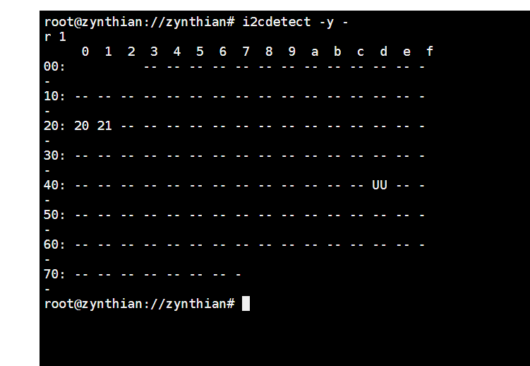
The problem is now trying to implement the second MCP23017. Ive got it on the same breakout board as U1, and it has the same INT A and INT B, SDA and SCL pins.
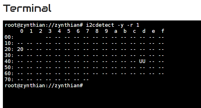
It registers at address 0x21.
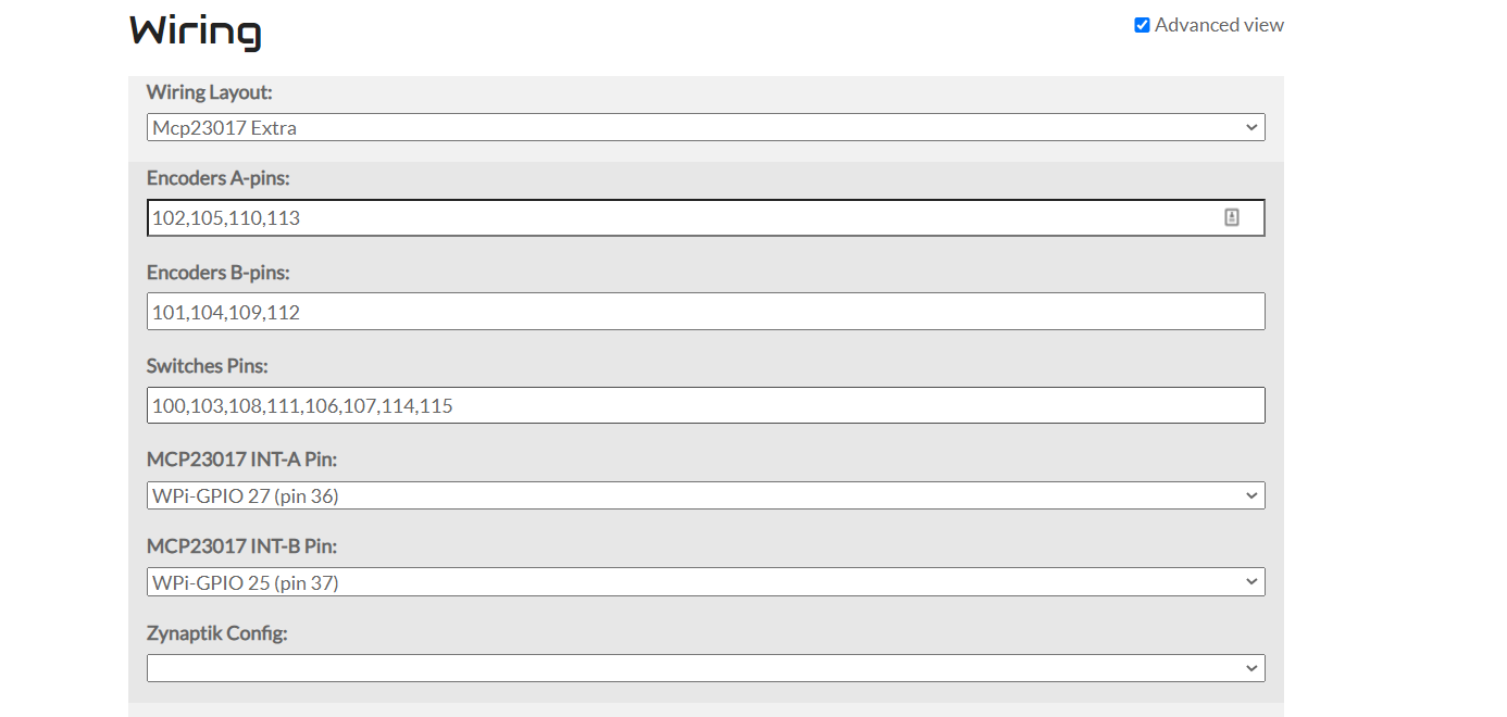
The problem is that as soon as I enable the 16xSwitch section in webconf, it knocks out any input from U1, ie the encoders and S1-S4 stop working completely. The zynth is still functional and touch/mouse input works, but any inputs connected to U1 stop working.
Im guessing theres some sort of communication error between U1 and U2, but after lots of reading and tinkering im getting nowhere. I hope some of you good people have some suggestions.
First of all, congratulations for your funny Zyn-journey! This fun is the kind of feeling that we all share on this forum
I never tried to share the same interrupt pin by 2 ICs and i’m not sure if this could work. The official hardware uses different interrupt pins for every IC:
0x20 with interrupt pins13 & 7 for the first MCP23017 (currently integrated on the ZynScreen)
0x21 with interrupt pins 36 & 37 for the second MCP23017 (optionally soldered on the zynaptik circuit)
The software configure 2 interrupt calls, one for every IC. So, probably, this is the real problem. When the zynaptik’s IRQs are configured on the same pins, they replace the zyncoder’s IRQs.
Try using different interrupt pins and it should work …
Currently you can’t configure Zynaptik’s MCP23017 interrupt pins from webconf. It’s hardcoded on the C library.
The AllInOne circuit (v2) uses different interrupt pins than the Zynscreen (v3 & v4), but both are on address 0x20. The Zynaptik’s MCP23017 uses the same interrupt pins than the old AllInOne (v2), but it’s on address 0x21. It can be a little bit confusing, so better stick to v2 or v4, and don’t try to mix.
Switches are switching, and im moving along to the midi bit.
Zynthian is the most forgiving linux project ive used where non standard and different hardware can be played with without the software getting into knots and having to reformat and start from scratch.