Hi, what a can of worms! i am trying to run an “All in one” and a “single MCP23017”( addressed like a “zynaptik MCP23017”) to get 16 additional switches. it is showing up as " I2C: [MCP23017@0x20, MCP23017@0x21]", which seems correct. only problem is that encoders and switched are not working if i turn on “16xdio”. Any suggestions?
What interrupt pins are you using for every MCP23017?
If you are using the AllInOne for the first MCP23017, you should choose different interrupt pins for the zynaptik. They can’t be the same.
Regards!
oh snap! i am using the same for both! can you recommend a good pair? will they be seen automatically (for the zynaptik). “All in one” needs to stay on 36 and 37
i got it! lifted the int pins on the all in one.
Fernando, one last sanity check question: in order to get stable switching (like for arrows and such) i needed to switch 5v with a 1.5k pulldown (think that is proper terminology) to ground… is that correct? The other (first) MCP23017 (for buttons and encoders) has buttons just shorted to ground…
Why not configuring all switches as “short-to-ground”? Unless you want to use this inputs as “gate” inputs, i would recommend configuring all switches (encoders & button switches) as “short-to-ground”.
For button switches, a 100nF debouncing capacitor is recommended. For encoder pins, 10nF gives very good results.
By doing like this, I never required pulldown/pullup resistors for GPIO pins when used for reading button switches or encoders.
The debouncing capacitors are “strongly recommended” ALWAYS.
The best!
2 Likes
Interesting! Is that done in “Switches Pins ?” i was thinking "Zynaptik Switch-xAction " automatically set them to “short to ground.”
When the “Zynaptik Switch-## Action” is set to “midi notes”. There is no trigger when shorting to ground. There is a trigger when the wire is touched (like cap sense???). Are the “internal pull-up (or pull-down)” resistors configured in the code? The other 4 buttons (on the 0x20) work flawlessly.
By default, zynaptik switches work like “gates”, so they triggers when going from 0 to 5V.
It can be changed by software, but this is the default behaviour.
Regards!
1 Like
Is there an easy way to have 8 (out of the 16) that are “short to ground” triggered like the 4 buttons on 0x20? i have tried a bunch of things including giving them numbers in “Switch Pin” list like 200,201,202…
It’s the easier solution for sure.
Well done!
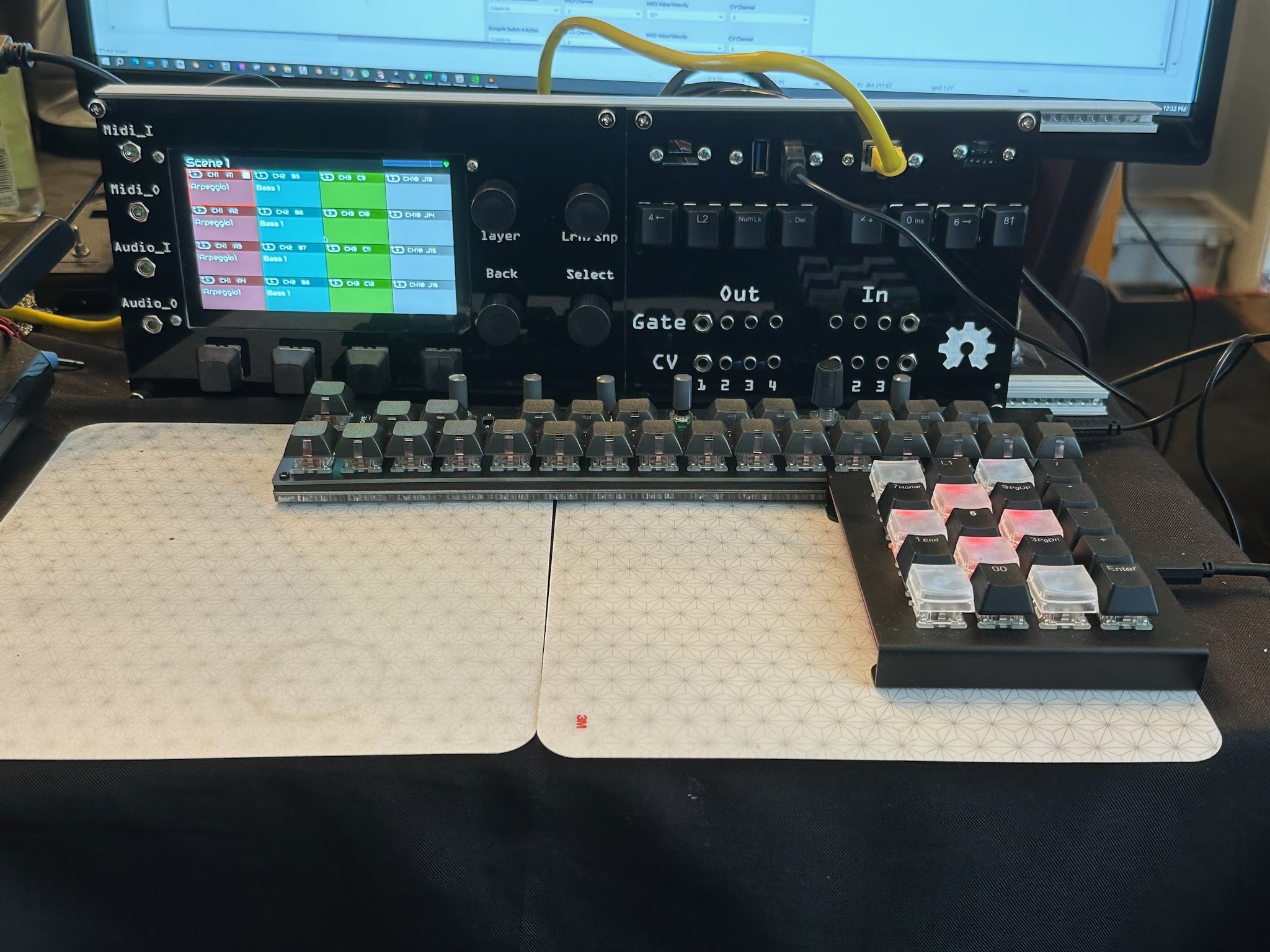
BTW, your zynthian setup is really cool. I love it! Could you send more detailed pictures and explain a little about it?
Thanks
2 Likes
i sure will ![]()
Hi,
I hope it is ok to bring this old thread back, but my question is related to the discussed topic.
I am using 2 MCP23017 in my DIY setup, too. The first at 0x20, with interrupts 13,7 and the encoder extra option. I wired the 4 additional switches short to ground without capacitors and that seems to work.
But I have no clue on how to wire the additional 16 switches on the second MCP23017. It is configured as 0x21 with interrupts 36 and 37 and the best solution I could achieve was that all switches are triggered randomly. I tried it with 10k pulldown resistors and like the other 4 switches short to ground.
When I understood Fernando correctly, short to ground would be sufficient but with an additional 100nF capacitor per switch, like this:
GND ----> Switch 1 ----> 100nF Cap ----> GPA0
The MCP23017 has the internal PullUp resistors activated and the capacitor would “extend” the time the switch is pressed a little bit, so that the state change can be detected more clearly? Is that correct? (I clearly have very little knowledge about electronics as you can see ![]() )
)
My goal is a working DIY Zynthian Mini and the only major thing missing are the 16 buttons.
Would it work like this and if so what configuration do I have to add in the wiring screen in addition to the “encoders extra” setting.
Thanks
Nils
Hi Nils!
All the V5 schematics are available in the zynthian-hw repository:
Regards
1 Like
Thank you. I tried unsuccessfully to figure this out before by reading the files from the repo. But now I have installed Kicad, opened the v5 files and found everything I wanted to know ![]()
If someone reads this later: the schematics I posted before was wrong. Correct is:
GND ------ Switch1 ---------- GPA0
                         |
GND --- 100n Capacitor --
In V5, 47nf are used for the switches and 10nf for the encoders. In the Zynthian Mini 100nf are used for the switches and since you also recommended 100nf,I will try it with these.
Best
Nils
2 Likes