I’m almost done with my first Zynthian build, but having an issue with the MHS35 screen that I had lying around.
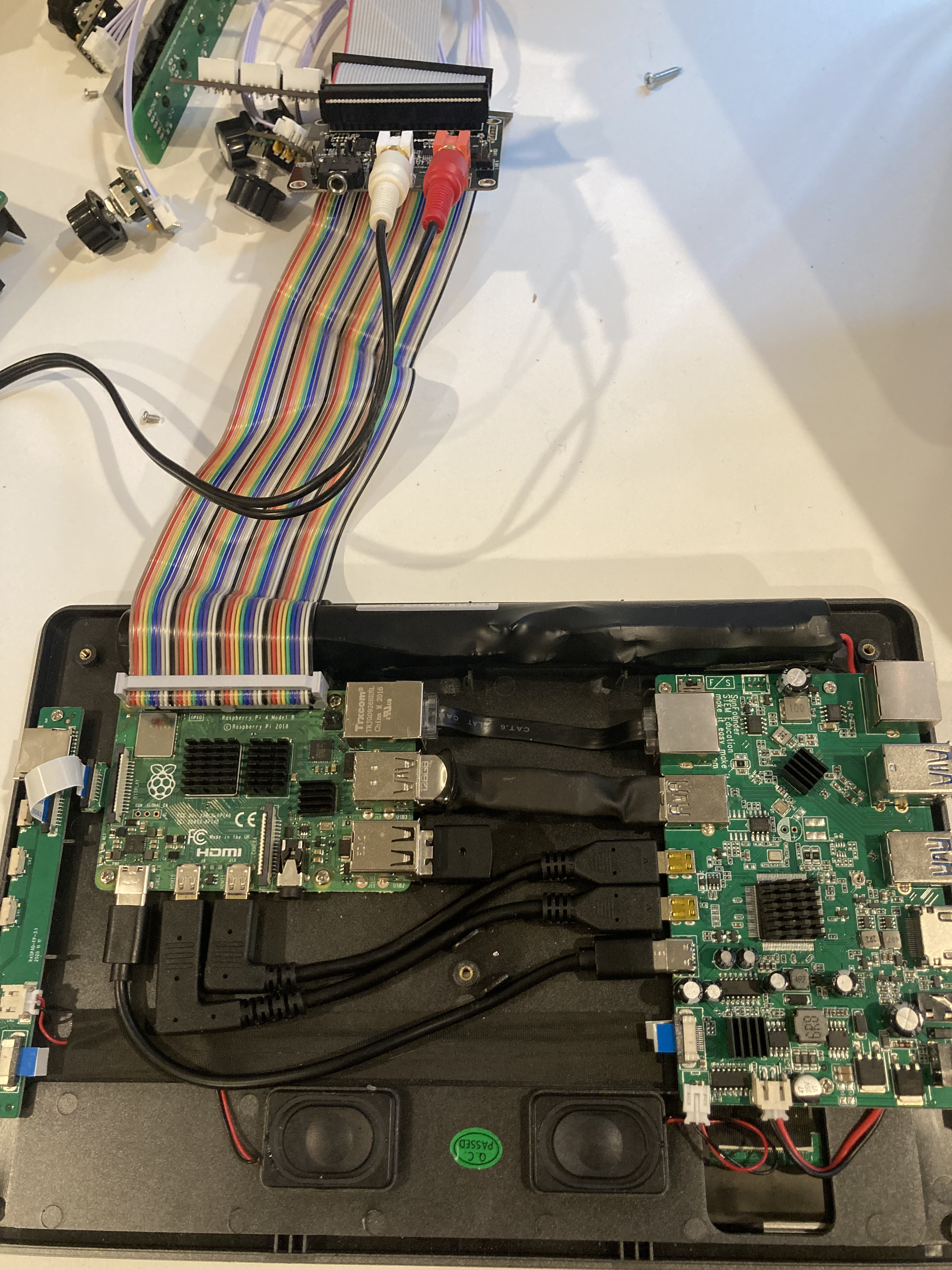
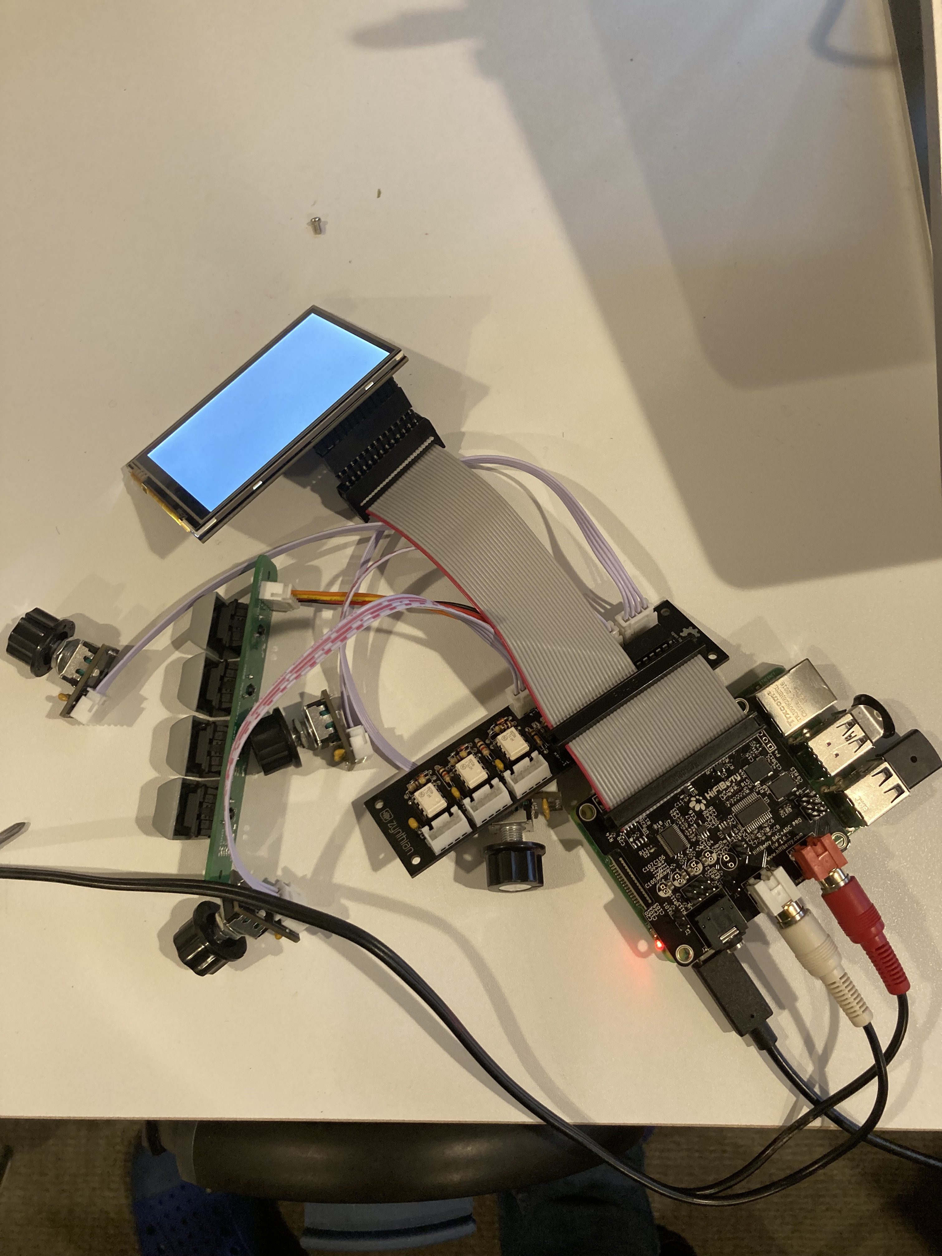
I have successfully gotten the display to work with a RPi 4 and the Hifiberry DAC ADC pro. Display, touch, audio out, and USB MIDI all work. However, when I added the official Zynthian Basic Kit V2 the screen won’t work. Fearing I built the Basic Kit wrong, I connected everything to a RasPad v3 to verify. All the encoders, plus the amazingly clicky CherryMX switches I added in place of the Zynscreen buttons, worked perfectly. I haven’t yet wired up the MIDI din ports, so haven’t tested those.
The problem appears to be related to connecting the screen via a cable. I have tried the ribbon cable that came with the Basic Kit as well as a metric shit-ton (technical term) of jumper cables. Neither scenario works. In fact, both cause the Pi to hang on boot.
Because I care not whether I fry this screen, I have tried attaching it to the ribbon cable in both directions. Good news! It didn’t fry anything, but clearly only gets power in one direction.
I’ve poked around for answers here in the forum and on the wiki, and all signs point to “this stupidscreenshould work”.
You say you “connected everything” to another Raspberry Pi? Do you mean everything or do you mean just the kit? I infer you mean that you tested the kit by itself and that seemed to work okay.
Please post some pictures of the connected devices when it is not working. It might help us get a better idea of what is connected and how.
Sorry. that was not clear! when i say i connected everything, i mean everything except the screen. in other words, the RasPad has a touch screen that acts as a Generic HDMI device. so i simply moved the Pi, the Zynthian Kit, the HifiBerry and all the dangly bits to the RasPad case/screen.
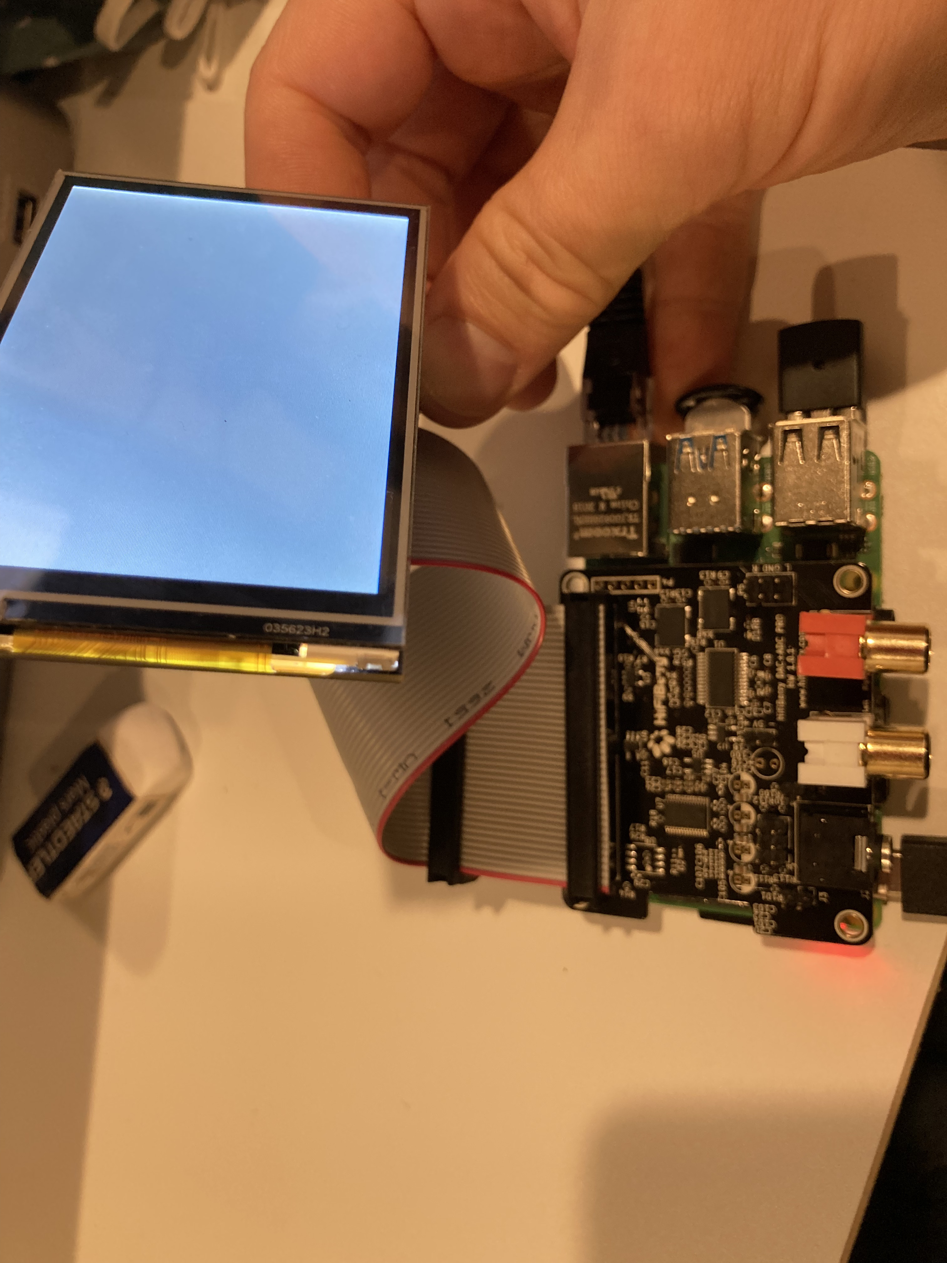
In the first 2 images below, Zynthian works perfectly, all of the knobs and switches work. However, in the last image it only works headless. adding the MHS35 screen to the official ribbon cable causes the Pi to hang on boot.
does that help clarify the mess i have created for myself?
To be clear, at first i wanted to turn the Raspad into a Zynthian, but i was unable to cram everything inside the case and, honestly, it’s just way more screen than I need. Hence my attempt to get the MHS35 working. This has gotten me thinking however, that it might be cool to package up the sound card, Zynthian expander, and all the knobs and switches in their own box with a GPIO header to connect to any Pi/Screen combo in seconds
First observation is that the MHS35 is plugged in the wrong way around. If connected directly to the RPi, it would suit over the same area as the RPi but you have turned it through 180°. So, try to flash a standard Raspberry Pi OS image and configure to use the MHS35 with only that screen connected directly to the Pi. You will see if the screen is still working after its abuse .
That was my thought as well! It is totally backwards. But the other direction it does literally nothing - no back light, no nothing. Not even the faintest flicker.
I also know that the screen still works after blatantly connecting it backwards because if I remove the ribbon cable and Zynthian PCB, and connect it directly to the headers on the Hifiberry, the screen works fine. It only doesn’t work when there is a cable of any sort between the screen and the headers. This is why I’m totally confused! Why would the ribbon cable prevent the screen from working? Simply a bad cable? Should I test continuity of all the wires going to the screen?
There are a few reasons that adding the cable might stop the screen from working. Here are a few:
Faulty cable: Test continuity of each pin. Test for short circuit between adjacent pins. Try another cable.
Wrong cable - Are all the pins extended, e.g. does the cable have sufficient conductors. (I see you are using the reduced conductor end of the cable.
Inductance - long parallel cables allow transmission of high frequency signals between conductors. The longer the run the more likely this will be an issue. It may be that the screen is particularly sensitive to such interference and the cable is too long. Similarly the capacitance of the cable may increase slew rate of signals which can stop it working.: Shorter cable.
Different test scenario - we can sometimes change more than one thing whilst testing: be sure that the only thing you change between tests is the cable to validate it is the likely cause of the change. That includes hardware configuration, physical positioning, software configuration, etc.
Faulty cable: Test continuity of each pin. Test for short circuit between adjacent pins. Try another cable.
i checked continuity of all the pins and it all looks good. i think i can rule out a faulty cable.
Wrong cable - Are all the pins extended, e.g. does the cable have sufficient conductors. (I see you are using the reduced conductor end of the cable.
i marked the same side of each header with a red Sharpie and made sure i had everything properly connected. guess what @riban! you , me and Common Damn Sense® were wrong! the “wrong” orientation is actually the right one
Inductance - long parallel cables allow transmission of high frequency signals between conductors. The longer the run the more likely this will be an issue. It may be that the screen is particularly sensitive to such interference and the cable is too long. Similarly the capacitance of the cable may increase slew rate of signals which can stop it working.: Shorter cable.
i don’t know a great way to test whether inductance is the source of the problem, but i did connect the MHS35 to the “middle” header on the Zynthian ribbon cable and it exhibited the same behavior. since that is a very short distance (~2cm) my guess is that either that’s not the source of the issue or this particular screen is so crappy that any distance from the header is too far.
Different test scenario - we can sometimes change more than one thing whilst testing: be sure that the only thing you change between tests is the cable to validate it is the likely cause of the change. That includes hardware configuration, physical positioning, software configuration, etc.
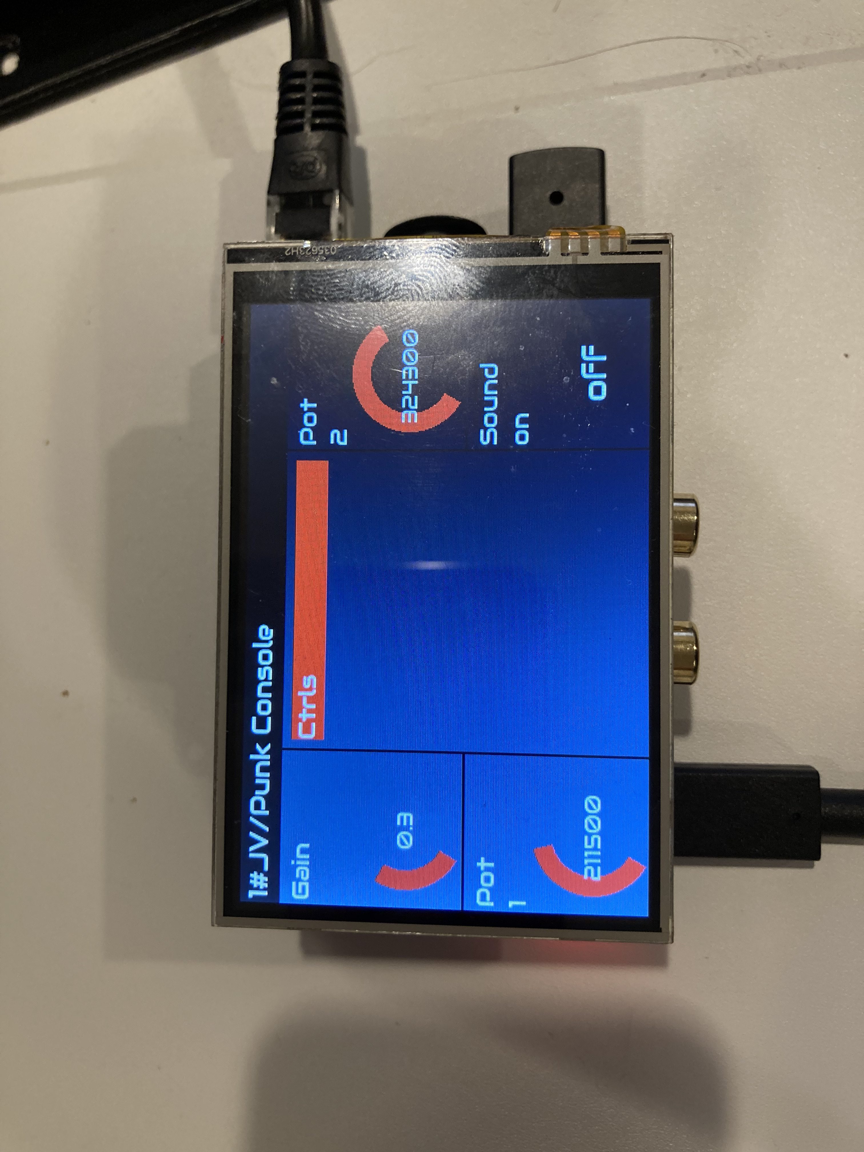
I was able to test this and the screen is still behaving like a stubborn child that insists on having all of the candy or none. see photos below.
I’m pretty sure the pins on the header will be reversed did to the male/female conversion. If you think about the cable connecting to pin 1 then consider the screen socket connecting to pin 1 then how the cable connects to the screen you should see the discrepancy.
I too list too much time to making a screen like this work and vowed never again… but was then gifted a Trojan horse by our friend @wyleu so lost another day of my life. You don’t get them back you know? So, is the screen is nearing you then move on.
There was a 5" screen someone found recently which looked good. It has capacitive touch and was that bit bigger to give better finger registration. (3.5mm really need fine tip stylus which in turn demands resistive membrane which is prone to variation, error and failure.) I have a 7" HDMI+USB capacitive touchscreen which is good but the extra connectors are awkward. That 5" used DSI which is good. Look in this forum. You should find regency to it.
[Edit] This was the 5" screen I was thinking of. Not tried it myself. It is available in three sizes. The original poster said it was awkward to mount bit it does have metal standoffs.
I agree 100% that the header orientation you describe is what makes sense. But continuity is continuity i do not argue with the beepy thing with wires hanging from it!
as I am less than a week from yet another birthday, I am very aware that you don’t get these days back.
thanks for taking the time to talk me thru the troubleshooting, @riban
Out of all the bit’s and pieces people bolt on to zynthians, screens seem to prove the most troublesome, as @riban says I passed him a touch screen that I did some work on way, way back, and the overall conclusions at the time was that even if the same chip sets were used how they were integrated and quite where the relevant code and context files lived had a considerable effect on the likelyhood of getting it working and that was before you tried to reboot it.
The saga of touchscreen alignment was another process that is heavily documented and the tool @riban wrote to tame that beast seems to have worked pretty effectively, as we don’t hear too many complaints of problems.
I tend to go for larger screens simply because they are more readable with older eyes, but if you are self building the screen and it’s mounting define many of the constraints with overall design, especially if the pi mounts directly on the screen ( thereby avoiding the ribbon cable). in this situation the connector positions are defined in relationship to the screen and that will need consideration if you don’t want to end up with a lot of local cabling to get the required functionality out of whatever box it all ends up in. It’s worth considering providing a separate power implementation to power screen and pi and dispense with the Pi’s power connection for instance.
The IDC socket on the ribbon cable is backwards! What was happening was that either way I connected the screen to the ribbon cable was wrong because row 1 on the was connected to row 2 on the ribbon and vice versa.
should be easy to solve my issue, but I wanted to post here in case anyone else runs into this. more importantly, since this ribbon cable was purchased recently from the Zynthian shop, I wanted to make sure someone knows about it in case it was a bad batch!
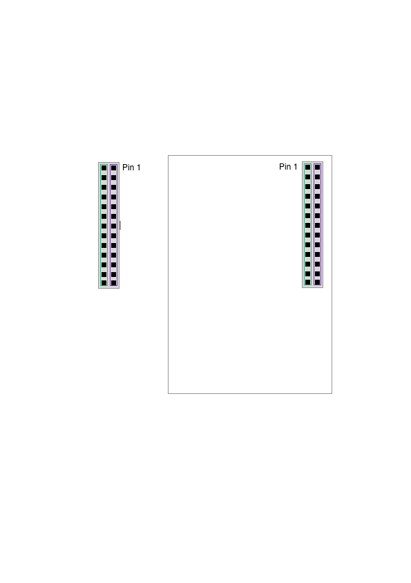
it’s not super easy to see in this shot, but hopefully this helps clarify. You can sort of see the rows of wires criss cross in the middle. and you should never cross the streams.
I refer the gentleman to the answer I have previously . There is no way the screen can be connected currently with that cable at that orientation.
The cable is fine. Two 40-pin connectors pointing one way and one 26-pin connector pointing the other way. This is the correct cable for Zynthian components but not for your screen.
I would have thought plugging into the 26-way the opposite way to how you have plugged it should give the right orientation and hence may work if it has sufficient pins connected. Your third picture shows an odd interface between the cable and screen which I can’t quite see properly but I think the screen has 26 pins and that connector looks the right orientation, just connected to the screen incorrectly.
both are top down views. on the left is the IDC socket coming from the ribbon cable intended for the screen. on the right is the top down view of the screen in the orientation that it would connect directly to a Pi (imagine you have x-ray glasses and you’re looking thru the screen). the green row would mate with the green row and purple withe purple. note that the ribbon expects pin 1 to be top right. the screen expects it to be top left. the rows are flip-flopped! so that rotating either the screen or the cable does nothing. when i was rotating the screen, Pin 1 would then mate with the bottom right of the header, which is not pin 1.
What my last photo was trying (and failing) at showing is that I effectively had to switch the rows because no orientation mates pin 1 to pin 1 in my case. Based on my very limited understanding of what’s going on inside that ingenious little IDC socket, if i simply rotate it 180 deg then pin1 on the ribbon cable would move to the green row in my diagram and I can dispense of all the pokery jiggery I am doing right now to make it work.
Yes. In the most recent photo, I used male to male jumper wires to test my theory that the rows are reversed. I have a 26-pin male IDC box header on the way that I plan to attach to the end of the ribbon cable to simplify the connection.
IDC connectors work by having fork like blades that pierce the insulation and make contact with the conductor. The IDC female headers are configured so that pin 1 always connects with the outermost conductor. This means that pin 1 on all connectors on the cable are connected together. The female connector presents pin 1 on its left bottom most pin when looking into the holes. The male header presents pin 1 on its left top most pin when looking down onto the pins. The female connector on the screen is designed to plug directly into the male header on the Raspberry Pi. This means that you can’t use a straight connector to link the female cable connectors to the female screen connector. In fact you may struggle to find any connector that will do this and have to resort to a PCB with two male headers connected in parallel (on the same side of the PCB), plugging the screen into one and the cable into the other.
The Zynthian cable is designed to mate with a screen that presents on a 26-way male header.
[Edit] @hugenerd your picture of the headers is wrong. Both female sockets have their pin 1 on the same pin so when you turn one through 180 degrees to mate with the other, pin 1 faces pin 2.
Now it all makes sense! That’s why it only works if I “flip flop” the rows - because I’m mating female to female.
This is what I plan to do!
@riban thanks for your patience in helping drill into my think skull how an IDC connector works!
What surprises me most is that I’m the first person to build a Zynth with an off-the-shelf screen and no clue that 2 female IDC sockets can’t be patched together with simple pin headers. Every 3.5” screen I’ve seen on Amazon, for example, has a female header (makes sense since it’s meant to attach directly to a Pi). This thread now exists as reference, but it’s a slow burn. Would it be useful to future generations to add a bit about this in the wiki for quick reference?
Thanks again for sticking with me until I understood the mess I had created
Maybe change the title of the thread to be more more descriptive, but that is after you have submitted the customary *
Most of the off the shelf screens have tended to fall into three or four distinct categories so you are on a thin and slender branch in this regard. IT’s interesting how chasing down a fault generally seems to lead to insight elsewhere. IT’s always a pleasure when the missing fact emerges!
It this makes no sense press on the moncle’d icon and some elements of what we do will be revealed .


 .
.
 i do not argue with the beepy thing with wires hanging from it!