
2 Likes
I really would like to build a Microdexed touch. Unfortunately I couldn’t find a full DIY Kit to order so I decided some weeks ago to order another amazing Teensy synthesizer project called Jeannie (Also presented here in Zynthian forum: https://discourse.zynthian.org/t/jeannie-8-voice-polyphonic-diy-synthesizer/ )
Ok, for the full kit you pay a bit more (like Zynthian full kit). You get pre soldered ICs on the PCB and very nice blue case. All remaining parts are included in the full kit and you have to build and solder a whole day with a very well illustrated manual.
If there would exist something similar with all parts like Zynthian and Jeannie I would order a Microdexed touch.
I have 5 pcb’s. I am slowly gathering parts.
I would take a Microdexed PCB. What is the price for letter from UK to Germany? Thanks in advance ![]()
Hello friends! How to connect a midi controller and manage settings on MicroDexed ? For example Korg nanokontrol.
Hi @rozhok ,
just connect your equipment to the USB-Host port of the Teensy (the connector is unsoldered on the Teensy-3.6/4.x, look here).
MicroDexed currently has a fixed CC mapping (see page 31) (I will implement a CC matrix later).
Does this answer your question?
Thanks a lot!
Hello everyone, how to make an arduino midi controller to control midi CC parameters by midi din5 in Micro-DEXED?I looked a lot on the Internet. I didn’t find anything.
It’s really not too complicated if you have a MIDI shield for the Arduino. You can use the excellent library from FortySevenEffects.
A small problem is that the Arduino has only one serial (hardware) interface, which you also need for programming. I always used the SoftwareSerial library for the MIDI interface (look at this example). Hint: take a deeper look at the examples. If you encounter problems while trying around, you can ask me.
1 Like
Dave from Notes and Volts has some neat aruino midi controller projects!
1 Like
Thanks, I’ll figure it out. It’s hard after a heart attack, I can’t concentrate, but I need to train my memory. I’ll try to do it.
1 Like
Control Surface might be a better choice for making a controller.
Thank you very much, Friends!!!
All the best for you!
Just an idea for easy building MIDI controllers:
… and another one: very flexible, not DIY and more expensive than DIY - but very cool:
Electra.One
1 Like
Hellohello friends! Am I making a midi controller to control micro-dexed correctly?
/*
This is an example of the “Bank” class of the MIDI_controller library.
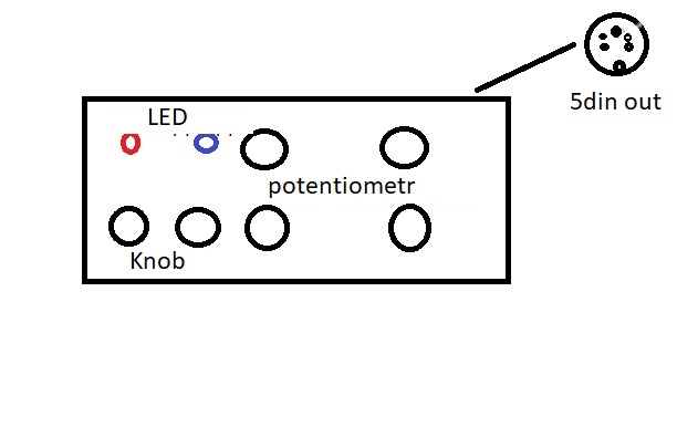
Connect 4 potentiometers to analog pins A0, A1, A2 and A3,
and two pushbuttons to pins 2 and 3.
Connect push buttons to pins 11 and 12, and 2 LEDs (+ current limiting resitors) to pins 4, 5).
When bank 1 is selected:
Potentiometer A is channel volume of track 1 (Controller number 0x07, MIDI channel 1)
Potentiometer B is channel volume of track 2 (Controller number 0x07, MIDI channel 2)
Mute button A is the mute button for track 1 (Note number 0x10, MIDI channel 1)
Mute button B is the mute button for track 2 (Note number 0x11, MIDI channel 1)
Connect push buttons to pins 11 and 12, and 2 LEDs (+ current limiting resitors) to pins 4, 5, ).
When bank 1 is selected:
Potentiometer C is channel volume of track 1 (Controller number 0x07, MIDI channel 1)
Potentiometer D is channel volume of track 2 (Controller number 0x07, MIDI channel 2)
Mute button C is the mute button for track 1 (Note number 0x10, MIDI channel 1)
Mute button D is the mute button for track 2 (Note number 0x11, MIDI channel 1)
The LED on pin 4 lights up.
When bank 2 is selected:
Potentiometer E is channel volume of track 3 (Controller number 0x07, MIDI channel 3)
Potentiometer F is channel volume of track 4 (Controller number 0x07, MIDI channel 4)
Mute button E is the mute button for track 3 (Note number 0x12, MIDI channel 1)
Mute button F is the mute button for track 4 (Note number 0x13, MIDI channel 1)
The LED on pin 4 lights up.
When bank 2 is selected:
Potentiometer J is channel volume of track 3 (Controller number 0x07, MIDI channel 3)
Potentiometer H is channel volume of track 4 (Controller number 0x07, MIDI channel 4)
Mute button J is the mute button for track 3 (Note number 0x12, MIDI channel 1)
Mute button H is the mute button for track 4 (Note number 0x13, MIDI channel 1)
Connect push buttons to pins 11 and 12, and 2 LEDs (+ current limiting resitors) to pins 4, and 5).
When bank 1 is selected:
The LED on pin 7 lights up.
This allows you to control multiple tracks with only a limited amount of physical potentiometers and buttons
*/
#include <MIDI.h> // Include the library
#include <MIDI_Controller.h> // Include the library
// Create 3 new instances of the class ‘Analog’, on pins A0, A1, A2 and A3
// that send MIDI messages with controller 0A (Effect_Control_1) on channel 1,
//controller A1 (Effect_Control_2)on channel 1 and controller A2 ( Effects_1) on channel 1 A3 and controller A2 ( Effects_2) on channel 1
Analog potentiometer_A(A0, MIDI_CC::Effect_Control_1_LSB, 1);
Analog potentiometer_B(A1, MIDI_CC::Effect_Control_2_LSB, 1);
Analog potentiometer_C(A2, MIDI_CC:: Effects_1 , 1);
Analog potentiometer_D(A3, MIDI_CC:: Effects_2, 1);
// Create a new bank that has 4 potentiometers per bank
Bank bank(2);
// Create 3 new instances of the class ‘Analog’, on pins A0, A1, A2 and A3
// that send MIDI messages with controller 0A (Modulation_Wheel_LSB ) on channel 1,
//controller A1 (Expression_Controller_LSB)on channel 1 and controller A2 ( Effects_3) on channel 1 A3 and controller A2 ( Effects_4) on channel 1
Analog potentiometer_E(A0, MIDI_CC::Modulation_Wheel_LSB , 1);
Analog potentiometer_F(A1, MIDI_CC::Expression_Controller_LSB , 1);
Analog potentiometer_j(A2, MIDI_CC:: Effects_3 , 1);
Analog potentiometer_H(A3, MIDI_CC:: Effects_4, 1);
// Create a new bank selector that changes the bank setting of the bank we just created
// It has pushbuttons connected to pins 8, 9, 10 that changes the bank setting,
// and 2 LEDs on pins 2, 3, that display the current bank setting.
BankSelector bankSelector(bank, { 8, 9, }, { 2, 3, } ); //multiple buttons with multiple LEDS
/* Alternatively, you can use arrays for the pin numbers:
const pin_t buttonPins[] = { 11, 12 };
const pin_t ledPins[] = { 4, 5, };
BankSelector bankSelector(bank, buttonPins, ledPins);
/_______________________________________________________________________________________________________________________________________/
void setup() {
// Add the created objects to the bank
bank.add(potentiometer_A, Bank::CHANGE_CHANNEL);
bank.add(potentiometer_B, Bank::CHANGE_CHANNEL);
bank.add(potentiometer_C, Bank::CHANGE_CHANNEL);
bank.add(potentiometer_D, Bank::CHANGE_CHANNEL);
// bank.add(potentiometer_E, Bank::CHANGE_ADDRESS);
// bank.add(potentiometer_F, Bank::CHANGE_ADDRESS);
// bank.add(potentiometer_J, Bank::CHANGE_ADDRESS);
// bank.add(potentiometer_H, Bank::CHANGE_ADDRESS);
}
/_______________________________________________________________________________________________________________________________________/
void loop() {
// Refresh the MIDI controller (check whether the inputs have changed since last time, if so, send the new value over MIDI)
// It also refreshes the bank selector
MIDI_Controller.refresh();
}
/*
Different Bank Select modes:
-
One toggle switch (latching switch)
When the switch is in the ‘off’ position, bankSetting 1 is selected
When the switch is in the ‘on’ position, bankSetting 2 is selectedBankSelector(bank, switch pin, BankSelector::TOGGLE);
-
One toggle switch (latching switch) and one LED
When the switch is in the ‘off’ position, bankSetting 1 is selected and the LED is off
When the switch is in the ‘on’ position, bankSetting 2 is selected and the LED is onNote: this mode is pretty useless, you can just connect the LED to the switch directly, without wasting a digital output pin on it.BankSelector(bank, switch pin, led pin, BankSelector::TOGGLE);
-
One momentary switch (push button)
Pressing the button switches the bankSetting:
When starting the program, bankSetting 1 is selected,
When the button is pressed, bankSetting 2 is selected,
When the button is pressed again, bankSetting 1 is selected,
and so on.BankSelector(bank, button pin);
BankSelector(bank, button pin, BankSelector::MOMENTARY); -
One momentary switch (push button) and one LED
Pressing the button switches the bankSetting and toggles the LED:
When starting the program, bankSetting 1 is selected and the LED is off,
When the button is pressed, bankSetting 2 is selected and the LED turns on,
When the button is pressed again, bankSetting 1 is selected and the LED is turned off,
and so on.BankSelector(bank, button pin, led pin);
BankSelector(bank, button pin, led pin, BankSelector::MOMENTARY); -
Multiple momentary switches (push buttons)
Pressing one of the buttons selects the respective output:
When starting the program, bankSetting 1 is selected,
When the second button is pressed, bankSetting 2 is selected,
When the n-th button is pressed, bankSetting n is selected.BankSelector(bank, { button 1 pin, button 2 pin, … , button n pin } );
-
Multiple momentary switches (push buttons) and multiple LEDs
Pressing one of the buttons selects the respective output and enables the respective LED:
When starting the program, bankSetting 1 is selected and LED 1 is on,
When the second button is pressed, bankSetting 2 is selected, LED 1 turns off and LED 2 turns on,
When the n-th button is pressed, bankSetting n is selected, LED n turns on, and all other LEDs are off.BankSelector(bank, { button 1 pin, button 2 pin, … , button n pin }, { led 1 pin, led 2 pin, … , led n pin } );
- Two momentary switches (push buttons)
Pressing the first button increments the bankSetting number,
pressing the second button decrements the bankSetting number:
When starting the program, bankSetting 1 is selected,
When the first button is pressed, bankSetting 2 is selected,
When the first button is pressed again, bankSetting 3 is selected,
When the last bankSetting is selected, and the first button is pressed again,
bankSetting 1 is selected.
When the second button is pressed, the last bankSetting (n) is selected,
When the second button is pressed again, bankSetting (n-1) is selected,
and so on.BankSelector(bank, { button increment pin, button decrement pin }, number of bankSettings);
-
Two momentary switches (push buttons) and multiple LEDs
Pressing the first button increments the bankSetting number and turns on the respective LED,
pressing the second button decrements the bankSetting number and turns on the respective LED:
When starting the program, bankSetting 1 is selected and LED 1 is on,
When the first button is pressed, bankSetting 2 is selected, LED 1 turns off and LED 2 turns on,
When the first button is pressed again, bankSetting 3 is selected, LED 2 turns off and LED 3 turns on.
When the last bankSetting is selected, and the first button is pressed,
bankSetting 1 is selected, the last LED turns off and LED 1 turns on.
When the second button is pressed, the last bankSetting (n) is selected, LED 1 turns off and LED n turns on,
When the second button is pressed again, bankSetting (n-1) is selected, LED n turns off and LED n-1 turns on,
and so on.BankSelector(bank, { button increment pin, button decrement pin }, { led 1 pin, led 2 pin, … , led n pin });
-
One momentary switch (push button)
Pressing the button increments the bankSetting number,
When starting the program, bankSetting 1 is selected,
When the button is pressed, bankSetting 2 is selected,
When the button is pressed again, bankSetting 3 is selected,
When the last bankSetting is selected, and the button is pressed again,
bankSetting 1 is selected.BankSelector(bank, { button increment pin }, number of bankSettings);
-
One momentary switch (push button) and multiple LEDs
Pressing the button increments the bankSetting number and turns on the respective LED,
When starting the program, bankSetting 1 is selected and LED 1 is on,
When the button is pressed, bankSetting 2 is selected, LED 1 turns off and LED 2 turns on,
When the button is pressed again, bankSetting 3 is selected, LED 2 turns off and LED 3 turns on.
When the last bankSetting is selected, and the button is pressed,
bankSetting 1 is selected, the last LED turns off and LED 1 turns on.BankSelector(bank, { button increment pin }, { led 1 pin, led 2 pin, … , led n pin });
Note: a switch is ‘off’ or ‘released’ when it doesn’t conduct. The digital value
on the input will therefore be HIGH (because of the pull-up resistor)
*/
Nice project, I had a teensy, all the electronics and hardware laying around, so I ordered some PCB’s and printed a case.
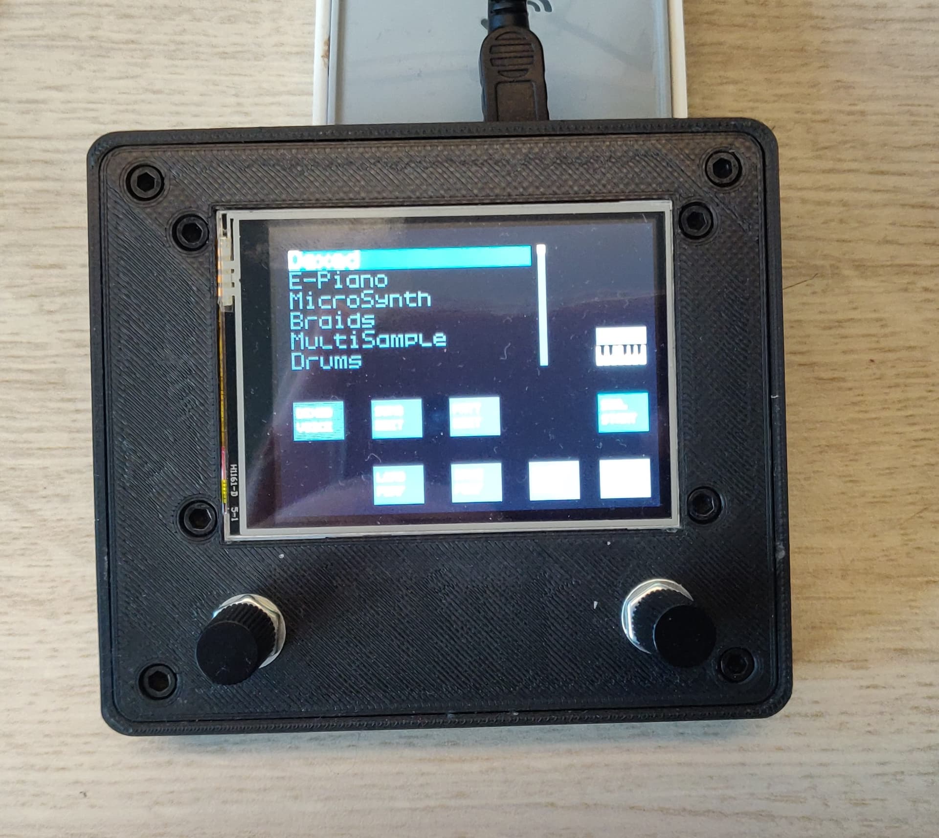
I have some pcb’s left, so if there are people who want to build one, PM me. I am located in the Netherlands.
Cheers,
Kees
4 Likes
")
5 Likes

3 Likes