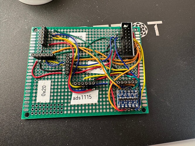
Mini V2 with ADS1115 and MCP4728

Hi,
a few month ago, I fell into another rabbit hole: modular synth. So now I thought it would be a good idea to add CV in and out to my custom build.
My build is basically configured like the Mini V2 but without the PCB. So I have:

  • RBPi4B
  • 5" Waveshare DSI Display
  • HifiBerry DAC+ADC
  • 2xMCP23017 (like Mini V2: 0x20 (100, Pin 5+6) and 0x21 (200, Pin 17+27)
    Keys and rotary encoders are configured like the Mini V2.

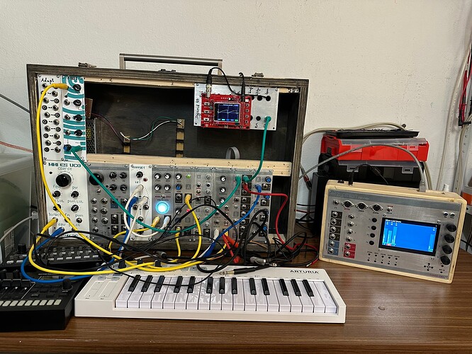
So I build a new case with 8 additional jacks, installed the latest oram, made sure everything was working as before and then added the ADS1115 and MCP4728.

This is the output of i2cdetect:

(venv) root@zynthian:~# i2cdetect -y 1
     0  1  2  3  4  5  6  7  8  9  a  b  c  d  e  f
00:                         -- -- -- -- -- -- -- -- 
10: -- -- -- -- -- -- -- -- -- -- -- -- -- -- -- -- 
20: 20 21 -- -- -- -- -- -- -- -- -- -- -- -- -- -- 
30: -- -- -- -- -- -- -- -- -- -- -- -- -- -- -- -- 
40: -- -- -- -- -- -- -- -- 48 -- -- -- -- UU -- -- 
50: -- -- -- -- -- -- -- -- -- -- -- -- -- -- -- -- 
60: 60 -- -- -- -- -- -- -- -- -- -- -- -- -- -- -- 
70: -- -- -- -- -- -- -- --   

I tried different wiring configurations. My best guess was V5 Zynface with Zynaptik Custom 4Xad, 4Xda and of course 0x48 for the ADS1115 and 0x60 for the MCP4728.

Is it possible to add the ADS1115 and MCP4728 to my configuration without creating a custom configuration in /zynthian/zyncoder or is it only possible to add the analog ins and outs when using the V4 configuration with only one MCP23017 and less buttons?

The main screen of the WebConfig shows both MCP23017 and the ADS1115 but not the MCP4728 for the I2C. Is it possible that I did the wiring wrong and the MCP4728 shows up with i2cdetect but can’t be detected by zynthian?

Oh and another thing: I used 3.3V for the MCP23017 before. In the Zynaptic diagram 5V is used. I assume I should switch to 5V to get the full range for the CV out from the MCP4728, correct?

I just checked the diagram again and opened the Zynface_V5 and had to laugh a bit because I hadn’t done that earlier. I assumed I had to configure 1 analog out for 1V/OCT and 1 for Gate. But according to the diagram I need another MCP23017 for gate in and out (this means 8 additional jacks and then I would have 8 unused digital I/O for other funny things)?

Any advice would be much appreciated.
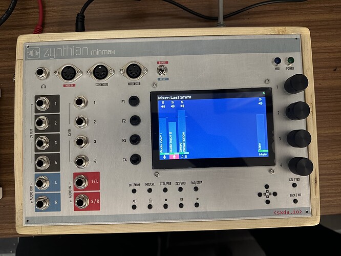
BTW: Here are some pictures of the new case and my setup (the modular, I built the last months, still not a musician)


13 Likes

Very nice!!!

1 Like

The I2C devices on the WebConfig dashboard are detected by parsing the i2cdetect output. Addresses between 0x20 and 0x27 are MCP23017 or MCP23008, between 0x48 and 0x4B are ADS1115 and the ones between 0x61 and 0x67 are MCP4728.
So my device is not shown, because it uses 0x60. I guess that’s a bug. There was a thread about the MCP4728 some time ago and I think the 0x60 address was added for custom hardware in the zyncoder but not in the dashboard.
Should I open a pull request for changing the 0x61 to 0x60?

After that I tried to change the voltage output via python to see if the chip is working. It is. :slight_smile:

Now I am trying to understand the zyncoder…

It’s super nice,@Nils! Congratulations for your magnificent build!!
FYI, current Oram has broken the CV/Gate interface. It must be fixed before you get working your device.

Also, you should consider adding your specific configuration to the zyncoder’s CMakeLists.txt file.

BTW, i can’t see your third MCP23017 in the i2cdetect output. I recommend you route your hardware accordingly to the configuration used by the V5_zynface:

	add_definitions(-DZYNAPTIK_MCP23017_I2C_ADDRESS=0x22)
	add_definitions(-DZYNAPTIK_MCP23017_INTA_PIN=5)
	add_definitions(-DZYNAPTIK_MCP23017_INTB_PIN=4)

Also, i can’t see your ADC chip in the i2cdetect?

Regards,

1 Like

The V5 mainboard includes a RTC chip in 0x60. The autodetection code consider this address is not available for other uses. It can’t make a difference between chips easily, so it considers that any chip in this address is a RTC clock, and we removed this address from the allowed addresses for the MCP4728.

In the zyncoder repository, you will find a little program, called:

mcp4728_set_address.c

that you can use for changing the address of your MCP4728 chip. It’s a simple process that you have to do once only for each MCP4728 chip. You need to connect the LDAC pin to RBPi’s GPIO. Check the program’s code:

#include <stdint.h>
typedef uint8_t bool;

#include <MCP4728.h>

#define MCP4728_I2C_ADDR 0x60
#define MCP4728_LDAC_GPIO 24

int main() {
	struct chip * mcp4728_chip = mcp4728_initialize(2, 3, MCP4728_LDAC_GPIO, MCP4728_I2C_ADDR);
	mcp4728_setaddress(mcp4728_chip, 0x64);
	mcp4728_deinitialize(mcp4728_chip);
	return 0;
}

This is for changing from 0x60 to 0x64, connecting the LDAC pin to GPIO 24. Modify as you like.

No. We are not going to open this range, sorry. At the moment, the address 0x60 is reserved for the RTC chip. There are still 7 available addresses for the MCP4728. Much more than enough!

Regards

1 Like

Thanks, I will do that.

Ok, I’ll wait and fix the other stuff that’s not working in my build in the meantime.

The third MCP23017 is still sitting at my desk, waiting to be soldered to a stripboard.
The ADC is at address 0x48.
That’s a good advice to use the V5_zynface config for this. I will do that.

Best

I mean the audio ADC :wink:

Ahh. I am not sure, but isn’t the HifiBerry DAC+ADC using I2S for this?

Each chip on the Hifiberry DAC + ADC is controlled by I2C and has a different address. You should have the audio ADC chip (PCM186X or similar) in the address 4A. It’s not there, so your audio input should not be working. Test it, please.

Regards,

1 Like

You are right. It is a PCM1861.

But audio IN and OUT are working.

But you should see the PCM1861 in the address 0x4A or 0x4B. It’s strange you don’t see it in the i2cdetect output.

Regards,

I had the hifi berry lying around, and some time ago I replaced the connectors. Maybe I damaged something in the process. I ordered a new one for the Zynthian and will compare the two when it arrives.
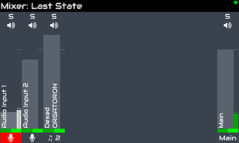
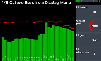
But for now it is working nevertheless. I don’t see the inputs in alsa mixer, only the output channels. But the input is there:


I added the third MCP23017 to the system and wired it like in the V5 zynface. The other 2 were already connected like in the V5:

MCP23017 0x20
INT A RBPi PIN 29, GPIO 5, WiringPi 21
INT B RBPi PIN 31, GPIO 6, WiringPi 22

MCP23017 0x21
INT A RBPi PIN 11, GPIO 17, WiringPi 0
INT B RBPi PIN 13, GPIO 27, WiringPi 2

MCP23017 0x22
INT A RBPi PIN 18, GPIO 24, WiringPi 5
INT B RBPi PIN 16, GPIO 23, WiringPi 4

After that I tried to change the address of the MCP4728. But I was not successful at first. I connected the LDAC to GPIO24 (RBPi pin 18), disconnected everything else, checked the presence of the MCP via i2cdetect, compiled and started the program:

cd /zynthian/zyncoder
cc -I /usr/local/include/ mcp4728_set_address.c -L /usr/local/lib -lMCP4728 -o mcp4728_set_address
./mcp4728_set_address

But the address didn’t change. I compared my wiring to the description of the process by riban.

Did you try that with oram?

Finally I used an Arduino to change the address.
There is a rather old MCP4728 library and small program from 2011 that includes everything needed. I just had to download the file mcp4728_library_v1.3_for_Arduino_1.0.zip, compile and upload the program to the Uno and now, I am quiet happy with the result:

     0  1  2  3  4  5  6  7  8  9  a  b  c  d  e  f
00:                         -- -- -- -- -- -- -- -- 
10: -- -- -- -- -- -- -- -- -- -- -- -- -- -- -- -- 
20: 20 21 22 -- -- -- -- -- -- -- -- -- -- -- -- -- 
30: -- -- -- -- -- -- -- -- -- -- -- -- -- -- -- -- 
40: -- -- -- -- -- -- -- -- 48 -- -- -- -- UU -- -- 
50: -- -- -- -- -- -- -- -- -- -- -- -- -- -- -- -- 
60: -- -- -- -- 64 -- -- -- -- -- -- -- -- -- -- -- 
70: -- -- -- -- -- -- -- --                         

Best

3 Likes

Hi Nils! Congrats by your success changing the MCP address. I didn’t tried with oram yet, but you were quite fast in finding the way with Arduino.

I already fixed the zynaptik code and my zynthian modular is working again, including CV/gate.
I didn’t commit the changes yet. I will do in Vangelis (testing branch) by tomorrow.

Regards

1 Like

Hi Nils!

I just pushed the changes in the vangelis branch. I’ve tested CV/Gate in and out and everything seems to work OK.

I made some loop testing, by connecting the CV/Gate output to CV/Gate input and adjusting the scaling and offset parameters from the “CV Settings” in the admin menu.

Also, tested CV/Gate input alone with my korg SQ-1 and it worked nicely.

You will note that vangelis branch have some extra improvements in the MIDI-IN routing menu, like the possibility of routing the internal Step Sequencer (Zynseq) and the MIDI player, including setting mode for each one (yes, you can set the ZynSeq or MIDI player in Active mode!!)

Enjoy!

2 Likes

Hi @jofemodo ,
thank you, that is great. I updated a completely new oram to vangelis and that worked great. The zyncoder is compiled with (hopefully) the correct config.
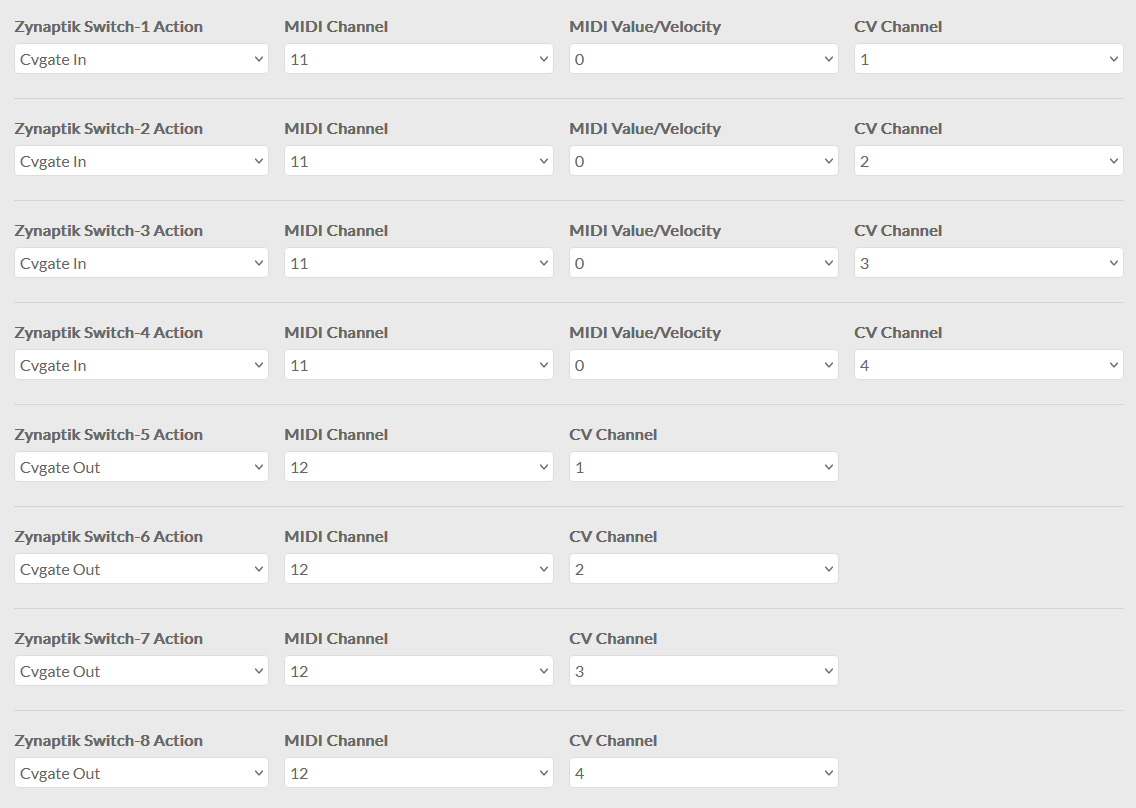
I wired the CV and GATE -IN and -OUT 1&2 (I only have 8 jacks in my case) according to the V5 Zynfac schematics. But I am not sure, how I have to setup the wiring layout.

I chose V5 Zynface for both wiring and customization profile.

But then Zynaptik Switch 1-16 and Analog in and out are set to None:
I configured it like this:

Is this correct?

I connected the Korg SQ-1 but I didn’t get any feedback in zyncoder_test, Midi activity icon and Midi-Log.
Best,

Is the zyncoder_test detecting your analog input/outputs? It should say something at startup.

I would validate CV-in / CV-out and switches separately before trying altogether. Using a variable known input voltage is better for testing CV in.

If you edit the “zyncoder_test.c” program you can enable some disabled fragments to test CV-in.

Also, you should put some value in the MIDI Value/Velocity field. A note with velocity=0 is a note-off :wink:

Regarding the wiring, i can’t help too much, as it’s you who better know how you routed things.

Cheers!

Hi @jofemodo
I could invest some time this weekend and finally got it working. :sweat_smile:

There were several issues, all of course in my wiring and configuration and not in the software.

The replacement for the Hifiberry DAC+ADC arrived and I installed it. There is still no I2C address appearing for the ADC with i2cdetect.

I studied the schematics of the V5 control and V5 zynface and stumbled upon the supply voltages for the MCP23017s and the other I2C devices. The 2 MCP23017 in the V5 control are powered by 3.3V. Then there is the connector to the zynface with 5V, GND, INTA, INTB, SDA and SCL. The MCP23017 on the Zynface, the ADS1115 and the MCP4708 are then powered by the 5V from the connector. This is because the CV and Gate use 5V. But aren’t then the I2C (connected to the other 3.3V devices), INTA and INTB (connected to the 3.3V expecting Pi) using 5V as well?

I thought, maybe this has something to do with the ADC of the Hifiberry not appearing. I had an quad level shifter lying around and since I had to rebuild my “I2C distribution board” anyway, I included this for SDA, SCL (only for the 3 5V ICs) and INTA and INTB of the third MCP23017.

The 5 I2C devices are still working after the improvement but no change with the Hifiberry. Maybe somebody else with the Hifiberry DAC+ADC (without Pro) can confirm this behavior?

There is now 1 thing, that might be a software issue: I connected 2 buttons to the 0x22 MCP (B0 and B1) exactly like the other buttons with 100nf de-bouncing capacitors. But for these 2 buttons I always get 3 readings for every button press (configured as Push UI action). I connected an oscilloscope and could only see 1 clear signal, so I think the wiring is OK.

Best
Nils

PS:
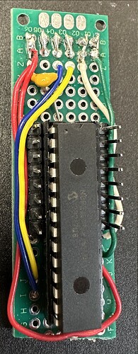
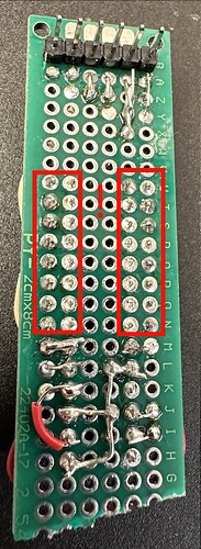
Here is 1 of the several issues, I had. Of course, this was not the first thing I checked. :rofl:

4 Likes