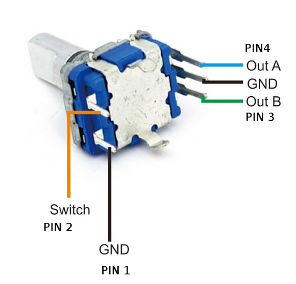
My finger is ready to pull the ‘buy’ trigger on one of these, but I thought I had better check here first… Are these compatible with Zynthian to run the rotary encoders, and if they are, any idea on what settings I might use?
The single should work.
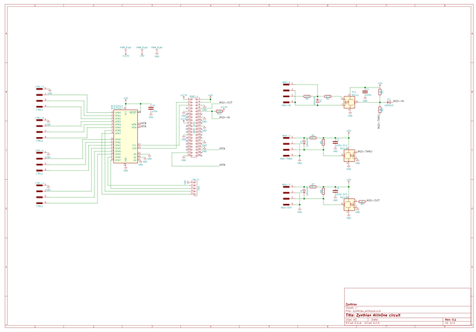
Should be self-explanatory if you can follow the zynthain All-In-One schematic. The trick will be either running GND from different pins on J1 for each encoder GND, or chaining them together.
zynthian_allinone.sch.svg
If you want to use arduino style encoder boards, you’ll also need to run a +V to each encoder as well.
ok, i think i get all that nearly… maybe i just can’t yet see where that gnd connects to… i would have hoped not from the gpio, because of the tft hat that has to go on as well.
As luck would have it, that lead me to this :-
which has visible breakouts for GND too… and it is cheaper.
Thanks, @smiths73v3 I will get there!
If you’re not in a rush and want to spend a little less, you could try one of these: https://www.aliexpress.com/item/32880817899.html?spm=a2g0o.productlist.0.0.315f2528pfled6&algo_pvid=53582668-c6f3-4abc-a13b-4d245b1fd3c5&algo_expid=53582668-c6f3-4abc-a13b-4d245b1fd3c5-18&btsid=1430e0e3-1a4c-48ad-bba4-cd1b40d3844d&ws_ab_test=searchweb0_0,searchweb201602_6,searchweb201603_53
yeah, they were the other option i looked at but i think i like the hats better
@MrBroccoli, might take much longer than you want to wait but I’m working on my own solution.
How do I find the right values to configure this with zynthian?
i2cdetect -y 1
Shows me 0x20 and 0x21 are available
i2cdump -y 1 0x20
Shows the some parameters that change if I turn dials.
How do I decode these values to the correct ones for zynthian?
Thanks
I’ve not tried that…
I’ll have a play.
This is what I see when i run :-
i2cdump -y 1 0x20
     0  1  2  3  4  5  6  7  8  9  a  b  c  d  e  f    0123456789abcdef
00: ff ff 00 00 ff ff 00 00 00 00 22 22 ff ff 00 00    ..........""....
10: ff ff ff ff 00 00 00 00 00 00 00 00 00 00 00 00    ................
20: 00 00 00 00 00 00 00 00 00 00 00 00 00 00 00 00    ................
30: 00 00 00 00 00 00 00 00 00 00 00 00 00 00 00 00    ................
40: 00 00 00 00 00 00 00 00 00 00 00 00 00 00 00 00    ................
50: 00 00 00 00 00 00 00 00 00 00 00 00 00 00 00 00    ................
60: 00 00 00 00 00 00 00 00 00 00 00 00 00 00 00 00    ................
70: 00 00 00 00 00 00 00 00 00 00 00 00 00 00 00 00    ................
80: 00 00 00 00 00 00 00 00 00 00 00 00 00 00 00 00    ................
90: 00 00 00 00 00 00 00 00 00 00 00 00 00 00 00 00    ................
a0: 00 00 00 00 00 00 00 00 00 00 00 00 00 00 00 00    ................
b0: 00 00 00 00 00 00 00 00 00 00 00 00 00 00 00 00    ................
c0: 00 00 00 00 00 00 00 00 00 00 00 00 00 00 00 00    ................
d0: 00 00 00 00 00 00 00 00 00 00 00 00 00 00 00 00    ................
e0: 00 00 00 00 00 00 00 00 00 00 00 00 00 00 00 00    ................
f0: 00 00 00 00 00 00 00 00 00 00 00 00 00 00 00 00 ................Hi,
I do not really understand where the problem is, it looks like everything IS working as it should.
i2c address is hardcoded in zyncoder library
The problem is that my dials still do nothing on the zynthian screen. On the hardware menu of the webgui, I need to chose the right hardware type, and then pick which pins should be configured, but I’m not sure what the values should be. I included the i2c stuff to show my dials are on the bus but I’m stuck now.
Ok, I see. It depends on how you have wired encoders to mcp23017.
- kit V3-pro correspond to this schematic: https://github.com/zynthian/zynthian-hw/blob/master/ZynScreen/OzzMaker/ZynScreen%20_v1.3.pdf
- kit V3 to that one :https://github.com/zynthian/zynthian-hw/blob/master/zynthian_allinone/zynthian_allinone.sch.svg
they differ only regarding INTA and INTB wiring
and maybe it helps:
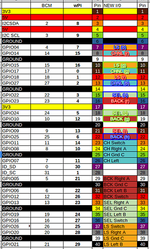
The coluorful table on this thread Encoder mapping for Direct I/O connection give details of what should go in the weconf setup … it’s the values from the WPi column…
I am not using either of these kits. I am using the “IO Plus” from the third entry on this post, which has mcp23017’s connected via i2c
Isn’t this table used when you directly connect the dials to gpio? I am not doing that. I am using MCP23017’s via i2c.
Well there is that, but I am VERY proud of having got the table together, so humour me a bit . . . 
The encoder pin mappings is there . . .
K, sure. Your colouring skills on this table are incredible, not only because they highlight the correct pin use for direct GPIO connections, but also they provide the perfect derailment for my issue. I couldn’t have done it without you. 

As for the diagram… I followed this wiring diagram original to wire up, but it doesn’t explain to me what values I need to add to the web conf page.
Depending on the diagram you have used (see my post above), and strictly follow ![]()
![]() of course, you juste have to chose the right kit, the pins wiring page will be updated accordingly.
of course, you juste have to chose the right kit, the pins wiring page will be updated accordingly.
When you say “have to chose the right kit”, does that mean I have to use zynthian hardware kit?

