ModMyPi MCP23017 pHAT

This is what I see when i run :-

i2cdump -y 1 0x20

     0  1  2  3  4  5  6  7  8  9  a  b  c  d  e  f    0123456789abcdef
00: ff ff 00 00 ff ff 00 00 00 00 22 22 ff ff 00 00    ..........""....
10: ff ff ff ff 00 00 00 00 00 00 00 00 00 00 00 00    ................
20: 00 00 00 00 00 00 00 00 00 00 00 00 00 00 00 00    ................
30: 00 00 00 00 00 00 00 00 00 00 00 00 00 00 00 00    ................
40: 00 00 00 00 00 00 00 00 00 00 00 00 00 00 00 00    ................
50: 00 00 00 00 00 00 00 00 00 00 00 00 00 00 00 00    ................
60: 00 00 00 00 00 00 00 00 00 00 00 00 00 00 00 00    ................
70: 00 00 00 00 00 00 00 00 00 00 00 00 00 00 00 00    ................
80: 00 00 00 00 00 00 00 00 00 00 00 00 00 00 00 00    ................
90: 00 00 00 00 00 00 00 00 00 00 00 00 00 00 00 00    ................
a0: 00 00 00 00 00 00 00 00 00 00 00 00 00 00 00 00    ................
b0: 00 00 00 00 00 00 00 00 00 00 00 00 00 00 00 00    ................
c0: 00 00 00 00 00 00 00 00 00 00 00 00 00 00 00 00    ................
d0: 00 00 00 00 00 00 00 00 00 00 00 00 00 00 00 00    ................
e0: 00 00 00 00 00 00 00 00 00 00 00 00 00 00 00 00    ................
f0: 00 00 00 00 00 00 00 00 00 00 00 00 00 00 00 00    ................

Hi,
I do not really understand where the problem is, it looks like everything IS working as it should.

i2c address is hardcoded in zyncoder library

The problem is that my dials still do nothing on the zynthian screen. On the hardware menu of the webgui, I need to chose the right hardware type, and then pick which pins should be configured, but I’m not sure what the values should be. I included the i2c stuff to show my dials are on the bus but I’m stuck now.

Ok, I see. It depends on how you have wired encoders to mcp23017.

they differ only regarding INTA and INTB wiring

and maybe it helps:

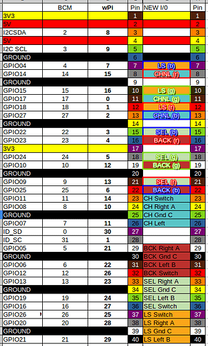
The coluorful table on this thread Encoder mapping for Direct I/O connection give details of what should go in the weconf setup … it’s the values from the WPi column…

I am not using either of these kits. I am using the “IO Plus” from the third entry on this post, which has mcp23017’s connected via i2c

Isn’t this table used when you directly connect the dials to gpio? I am not doing that. I am using MCP23017’s via i2c.

Well there is that, but I am VERY proud of having got the table together, so humour me a bit . . . :smiley:

https://discourse.zynthian.org/uploads/default/original/2X/4/43c3171a7e2b4b0dba535a20e0b2203d5e8a7498.svg

The encoder pin mappings is there . . .

1 Like

K, sure. Your colouring skills on this table are incredible, not only because they highlight the correct pin use for direct GPIO connections, but also they provide the perfect derailment for my issue. I couldn’t have done it without you. :stuck_out_tongue_winking_eye::+1:

As for the diagram… I followed this wiring diagram original to wire up, but it doesn’t explain to me what values I need to add to the web conf page.

Depending on the diagram you have used (see my post above), and strictly follow :roll_eyes::joy: of course, you juste have to chose the right kit, the pins wiring page will be updated accordingly.

When you say “have to chose the right kit”, does that mean I have to use zynthian hardware kit?

No, I mean in the webconf, under hardware, there’s a page calles ‘kit’ or something like this

Hmmm… This is even more confusing for me. Although i wired my rotaries like the kits do, they have extra components such as the midi inputs and outputs that I don’t have. I thought I should use “custom” at that menu, and then set the correct mcp23017 and corresponding values on the “wiring” menu.

I will try the kit settings now. Thanks.

Edit :- Nope… using “kit” instead of “custom” is very bad. It sets the screen and the soundcard to kit options, which are not the same as mine.

  • kit V3-pro is corresponding to mcp23017 zynscreen
  • kit V3 is corresponding to mcp23017 (encoders or extra if you use extra switch on the 4 mcp23017 pins that are not used by the encoders)

the “kit” settings also force the screen and audiocard options, so I have to use “custom”

Go custom.

Encoder A: 102,105,110,113
Encoder B: 101,104,109,112
Switch: 100,103,108,111,106,107,114,115 (the 4 last for extra switches)
these are for V3 (like the all in one board) and V3 pro (zynscreen)

If you wired it as the all in one schematic:
IntA : gpio 27 - pin 36
IntB : gpio 25 - pin 37

I now have two red encoders that seem to be responding to Interrupts on GPIO23 & GPIO14, that happen to coincide with MIDI event from the keyboards. Very pleasantly interactive !!

Yeah I was trying to work out what the numbers mean (except for that I have something wrong)

MCP23017 Zynscreen has the following settings… (does it have 4 more buttons as well?)

Encoders A-pins:
102,105,110,113

Encoders B-pins:
101,104,109,112

Switches Pins:
100,103,108,111,106,107,114,115

So we have 16 pins in the game and if I presume 100 is our start address and count the pins up. Is this how it works?

100 - ctrl-1 2 - GPA0 - Switches Pins
101 - ctrl-1 3 - GPA0 - Encoders B-pins
102 - ctrl-1 4 - GPA0 - Encoders A-pins
103 - ctrl-2 2 - GPA0 - Switches Pins
104 - ctrl-2 3 - GPA0 - Encoders B-pins
105 - ctrl-2 4 - GPA0 - Encoders A-pins
106 - sw-1 2 - GPA0 - Switches Pins extra
107 - sw-1 3 - GPA0 - Switches Pins extra

108 - ctrl-3 2 - GPB0 - Switches Pins
109 - ctrl-3 3 - GPB0 - Encoders B-pins
110 - ctrl-3 4 - GPB0 - Encoders A-pins
111 - ctrl-4 2 - GPB0 - Switches Pins
112 - ctrl-4 3 - GPB0 - Encoders B-pins
113 - ctrl-4 4 - GPB0 - Encoders A-pins
114 - sw-1 4 - GPB0 - Switches Pins extra
115 - sw-1 5 - GPB0 - Switches Pins extra

so I clearly have something wrong.


These are the settings i just tried, and i got no results at all.


The wiring diagram for my hat. The board does not connect the interrupts itself. If I connect the interrupts to 36 and 37 my pi wont boot at all.


These are the labels on my rotary encoders. I thought I should be connecting the switches to 106, 107, 114 and 115 but maybe I should be connecting to 100,103,108 and 111? I have the grounds all connected. Do I need to connect the +ve too?

I really don’t want to have to submit and buy the original zynthian board and controllers, or use all my pi gpio pins directly either. :pleading_face: