Thanks for the comments from everyone. The post that wolfpaw pointed me to gave me everything I needed to get it working I think.
I was using the new schematic as in the picture I posted above, but as I mentioned, I think that the switch pins are not labelled correctly for the config in the software.
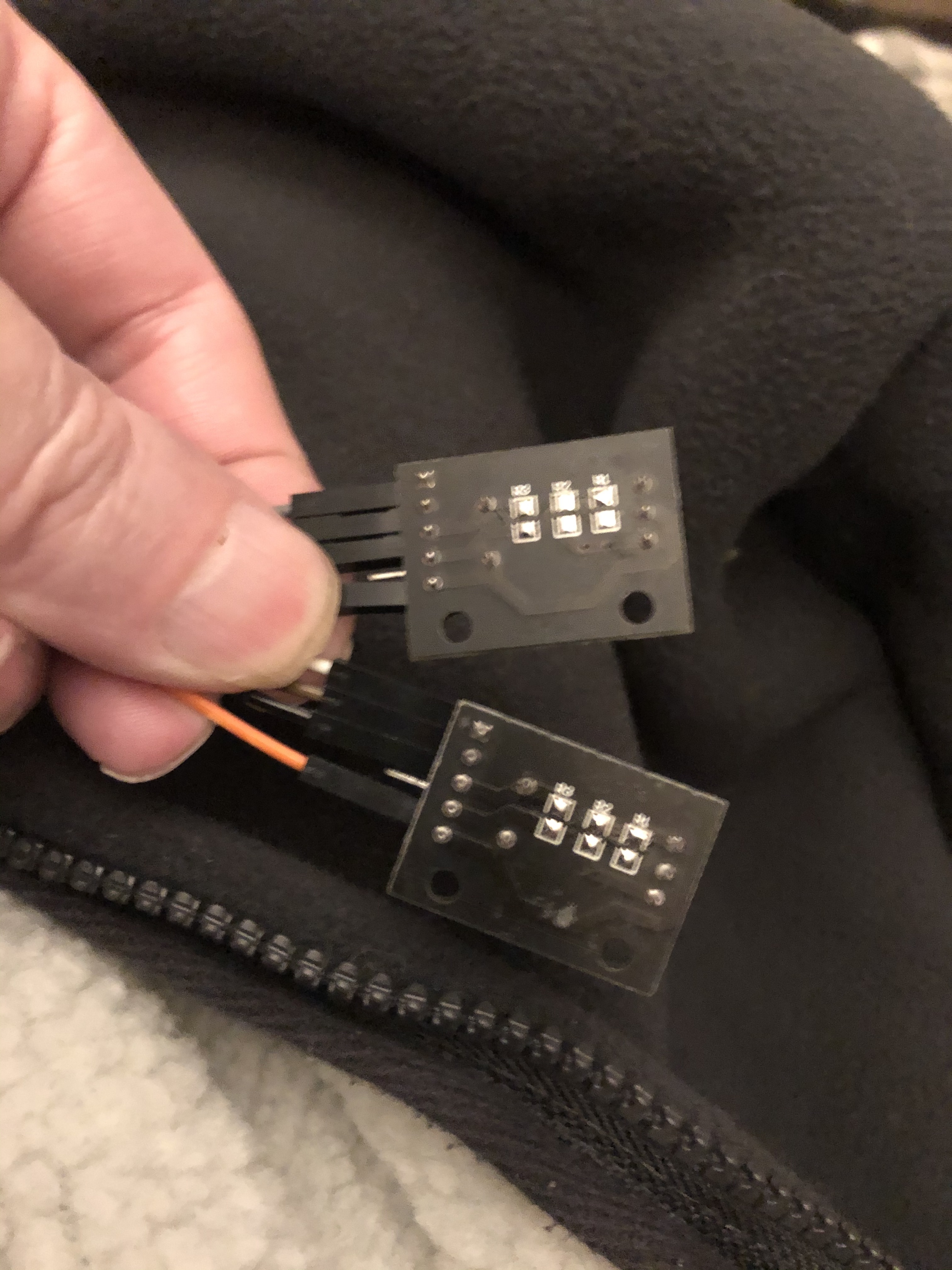
on my encoders, I have the GND,SW,DT and CLK connected - I found that you can leave the +5v off.
BUT, I have my switches connected to Gpb0, Gpb3, Gpa0 and Gpa3 on the expansion board and put either the DT or the CLK back to where the SW was.
For me, using the schematic, instead of having DT and CLK for the encoders, I had a switch wrongly wired ( but matching your diagram ), so for example, I had encoder DT for the clockwise and the switch connected for the anti clockwise, which is why I couldn’t understand why it wasn’t working.
My revised wiring for Smiths73v3 's diagram (Which I thought was the clearest and made most sense to me) is as follows:
GpB0 - SW (encoder 3)
GpB1 - DT (encoder 3)
GpB2 - CLK (encoder 3)
GpB3 - SW (encoder 4)
GpB4 - DT (encoder 4)
GpB5 - CLK (encoder 4)
GpA0 - SW (encoder 1)
GpA1 - DT (encoder 1)
GpA2 - CLK (encoder 1)
GpA3 - SW (encoder 2)
GpA4 - DT (encoder 2)
GpA5 - CLK (encoder 2)
I have removed all resistors from the encoders and connected the GND on each encoder to a separate GND on the PI I/O ( pind 6,9,14 and 20)
I’ve just carried out a test with the unmodified encoder I have ( purchased a set of 5 ) and it will not work with the pull up resistors in place.
If your encoder goes in the wrong direction when testing on the menus, just swap the DT and the CLK on the encoder.
Please test on your prototype, but this is how mine is wired and working at the moment.
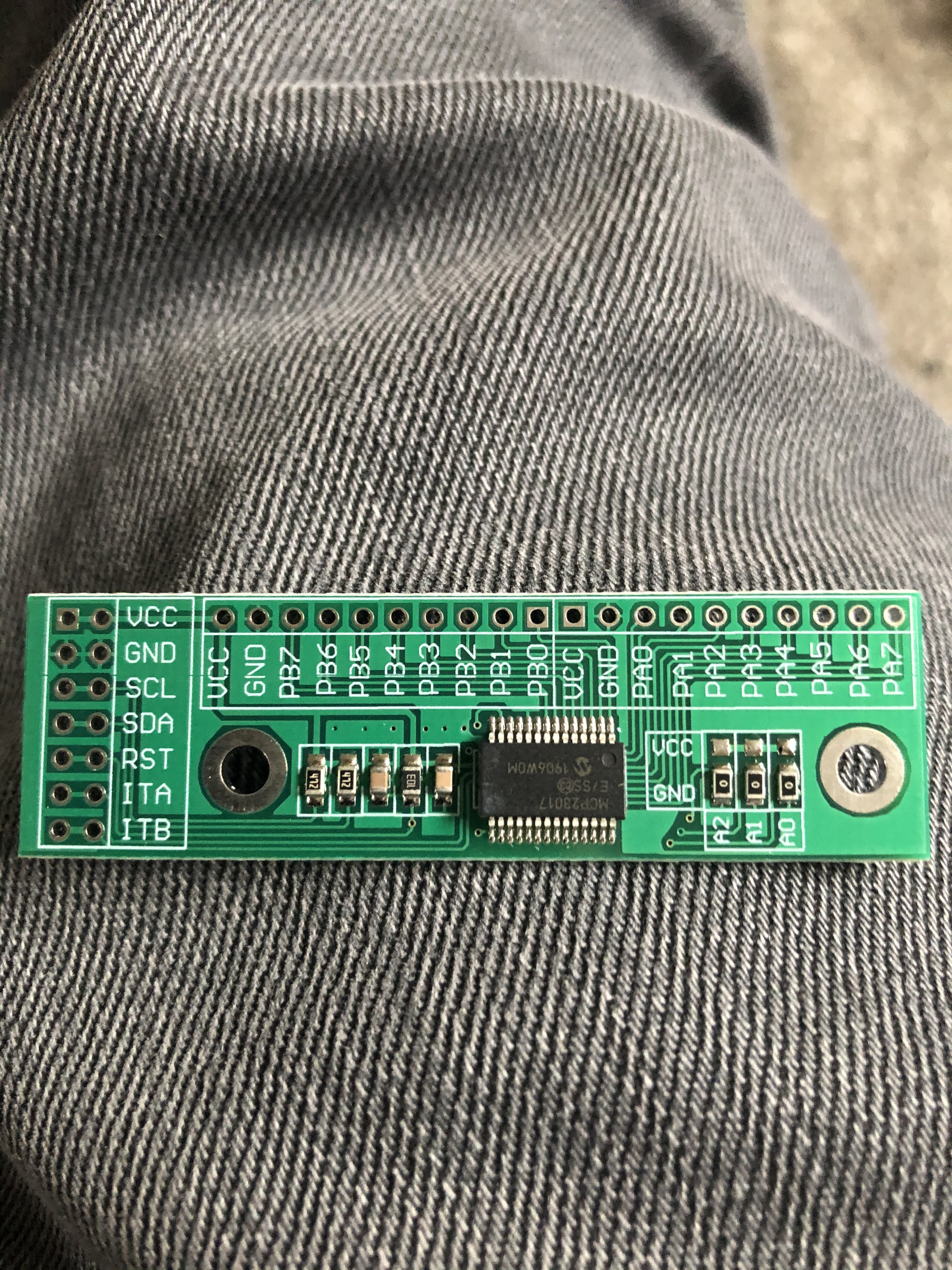
The extended I/O board is by dollartek and was about £6.50 ffrom Amazon. Reset pin is pre wired to be held at 5v (no need for a separate wire) and there are links on the board for the address setting (A0,A1,A2) which are set for address 20 by default (No changes needed with the current zynthian build).
I didn’t add the midi stuff, but I did add a 3.5mm audio jack to the DAC board.
Again, Thank you all for the help 
Ian.