New build with 5 pin encoders and pre built mcp23017 board

Hi all.
I decided to build the zynthian at last.
Rather than buy the kit, I decided to go open source as I already have most of the parts already - Dac+ board and 3.5” touch display, pi3 etc.
I don’t need 5 pin din midi connectors, so left those off. Usb midi will be fine.
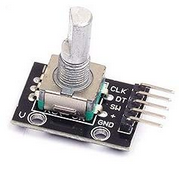
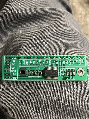
I got 20 step 5 pin encoders from amazon and a pre built mcp23017 board also.
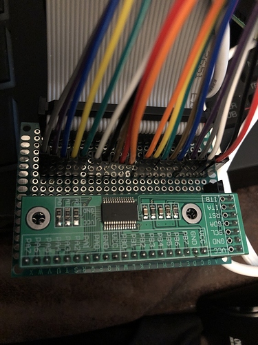
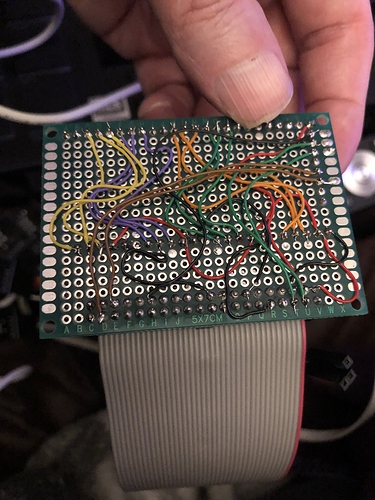
I mounted the pre built board on a prototype board and added a 40 pin header for a ribbon cable.
I got a PI multiconnector board from amazon too - gives 3 sets of 40 pins to connect to means I don’t have to build a cable.
Some rough looking wiring on the back and I have a prototype ready to test with just a few hours work.

My issue is with the encoders.
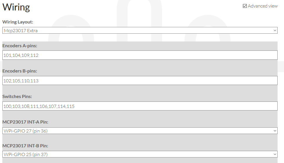
I have tried various config settings for the wiring, but can’t get the encoders working properly.
I have the board with a default address of x20.
I can de solder a jumper from A0 to give an address of x 21 or edit the software.
I read in a post below that joe has edited the software to account for this, so I’m not sure what to do for the best. I have never edited to software so don’t know where to start, I’m fine with electronics though.

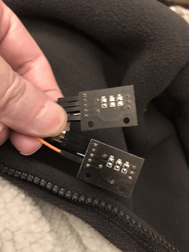
I have attached a couple of pictures which might help give you an idea of what I’ve done.
Any advice would be great :slight_smile:

Can anyone point me to a guide to edit the software? or would it be easier to change the hardware for me? desolder a link and relocate it.

It seems that the buttons don’t work either… could be the address?

(upload://zlq2ifw4WOFYhuE5Q4wcCFrkyFc.jpeg)
2 Likes

I could only add two pictures, here are the boards.
The mcp board is great becuase it already has the reset pin held high and the A0,A1 and A2 pins are all held low, pull up resistors are included also.
I have SDA to pin 3 on the PI, SCL on pin 5 of the PI, INTA on pin 36 and INTB on pin 37.
All wiring was checked before powering up - I’m sur of no errors / shorts.

1 Like

I’m certainly no expert but its hard to make out the wiring from those images.

With respect to how it should be wired, and I’ve just made my own board recently…

Your SDA, SCL and INTA/B wiring reads right so maybe its the controller wiring

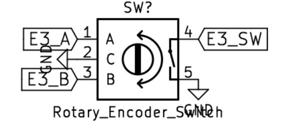
I see you have all 5 pins connected, are they connected like this:

encoder

So for example - button 4, which is a good one to test.

A > MPC B5
B > MPC B4
SW > MPC B3
you ground the other 2

Also, does the web config show up “GPIO Expander: MCP23017”

3 Likes

Thank you for the reply Simon.
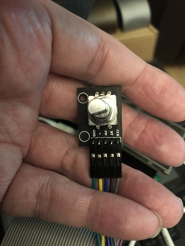
My encoders are a little different from you r diagram - they have a +5 and GND on them - 5 pins.
The switch does switch to GND, the same as your example.
I mean that when you operate a switch, the GND on pin 5 is connected to pin 4 and lowers the voltage to zero. Example, button 2 is connected to pins PB3, PB4 and PB5 on the expansion board, where PB5 is the switching signal.
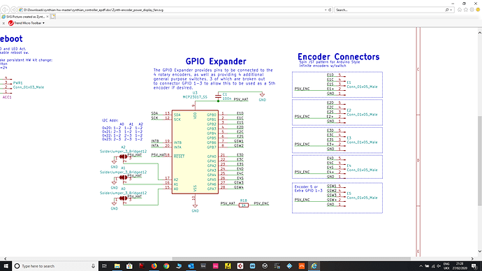
To be fair, I have basically copied the wiring from the sugegested ‘Hat’ example in the documentation (Picture below).
I have tried address 21 on the board today by shorting the links, but it stopped all functions when I did this.
If I run the gpio i2cd command, I can see the GPIO board on address 20, so I think that I have comms to the expander board working.

I think that my hardware is connected ok, but the software is not configured properly and I don’t know how to edit it yet.
I’m ok with arduino software editing, but have not touched the rasp pi.
I currently use microsoft visual studio code for arduino / 3d printer firmware editing, I don’t know if I can use this for the PI?

Do you have any tips or links for how to edit the synthian firmware files? I downloaded a ready prepared link for an SD card initially, but it seems that I might have to start editing.

Once again, thank you very much for taking the time to reply and trying to help - it’s very much appreciated :slight_smile:

hmmm, I’ve never had to change anything in the software as mine just worked, though I did build my encoder boards from scratch. I’m pretty new to this myself, and electronics.

These are the plans I used.

AllinOneSchematic.pdf (1.6 MB)

zynthian_controller_single2_smd.pdf (13.4 KB)

1 Like

This has been discussed here: Starting my zynthian build: alternative LCD, DAC, encoders
Check out Sept 18 posts. The +5V connection can be left unconnected.

1 Like

Thank you very much both :slight_smile:
The link you gave has lots of information.
It seems that the pull up resistors on the encoders that I am trying to use are causing issues.
I’ll desolder them and see how it goes!

Thanks again,

Ian

Hi @Ian_G,

The schematic you are looking at is part of a hw fork I am working on. I think it’s correct at this point. I have been able to use the 5pin encoders unmodified with +V, but I’m not sure if my setup is +5V or +3V. I’ll have to double check this weekend, but I don’t think that is your issue.

From the video it looks like you might have the pins to the encoders out of order. I had some issues initially, and I solved them by changing the wiring setup in webconf:

You should try this setup:

1 Like

Hi Smiths73v3, thanks for the reply.

Your shematic was the one that made most sense to me electronically, it seems to be very straightforward.
I have the same setup as you, but with the encoder A and B pins reversed – 102,105,110,113 are on the top line.
I imagine that it would just change the direction of rotation of the encoder.
I have de soldered the 10k resistors from all of the encoders and I’m having better responses, but I’ve changed the wiring for the encoders too. Is it possible that we have some pins crossed over on the schematic?
It seems that on the all in one diagram, Gpb0, Gpb3, Gpa0 and Gpa3 are the switches, but we have those down as for the ‘data’ pin.
I have swapped the switch and data pins on the encoder and have got what appears to be encoder functions ( 10k pull ups desoldered ).I also disconnected the +5v from each encoder and it does not seem to make a difference.
I have one encoder with the resistors still attached and I’ll do some testing later on if I can to see how it functions.
Thanks for everyones help on this, It’s been a little tricky :slight_smile:
Ian

That’s correct.

1 Like

Yes this has been walked before.
In the ancient zynthian history encoders were hung off Pi i/o ports so not all options get fully examined.

There does seem to be two basic ( at least) designs of encoder board and encoder combinations, and perhaps this needs recognised, in the infinite map of cross connects this stuff can become.

The thread @wolfpaw98 linked, does cover this area, once you ignore my Motor61 ramblings. It’s one of reasons I like the 12c encoder boards.

Presumably press buttons all work? One problem with testing this is access to specific menus. Try sticking a mouse into the zynth and turn on the cursor from webconf.

Try going to screens that treat the list selection and screens that rely on control parameter.
At the end of the day as the encoder rotates that information needs to produce responses within the software, do you see any chatter as the encoder is rotated?

1 Like

@wyleu,

I had not thought that the encoders would be wired up differently for different 5 pin boards. Ugh.

I’ll see what I can work up as an encoder tester. I am wondering if I can determine the encoders config by pressing the button, and then CW, CCW rotation in order.

@Ian_G, Looks like I told you wrong, Sorry. The schematic is different than my current setup. I still think you don’t need to remove the resistors. When I tried that it lead to unstable switching for me, it mostly worked but occasionally a switch would register a long press when I did a short press…

The encoders have “GND, +, SW, DT, CLK”
image
So “EC,ED,ES” in the schematic correspond to each of these pins. ES is the switch, EC, and ED are the encoder lines.

So GPIOA0 = 100, and that gives Encoder 3 Switch on 102. A,B pins are on 100, and 101 (or reversed)

  • Encoder 3: A 100, B 101, SW 102
  • Encoder 4: A 103, B 104, SW 105
  • Encoder 1: A 108, B 109, SW 110
  • Encoder 2: A 111, B 112, SW 113

That should give you:

  • Encoder A Pins: 108,111,100,103
  • Encoder B Pins: 109, 112, 101, 104
  • Switches: 110,113,102,105,106,107,114,115
1 Like

Hi again all,
Thanks for the comments from everyone. The post that wolfpaw pointed me to gave me everything I needed to get it working I think.
I was using the new schematic as in the picture I posted above, but as I mentioned, I think that the switch pins are not labelled correctly for the config in the software.
on my encoders, I have the GND,SW,DT and CLK connected - I found that you can leave the +5v off.
BUT, I have my switches connected to Gpb0, Gpb3, Gpa0 and Gpa3 on the expansion board and put either the DT or the CLK back to where the SW was.
For me, using the schematic, instead of having DT and CLK for the encoders, I had a switch wrongly wired ( but matching your diagram ), so for example, I had encoder DT for the clockwise and the switch connected for the anti clockwise, which is why I couldn’t understand why it wasn’t working.

My revised wiring for Smiths73v3 's diagram (Which I thought was the clearest and made most sense to me) is as follows:

GpB0 - SW (encoder 3)
GpB1 - DT (encoder 3)
GpB2 - CLK (encoder 3)
GpB3 - SW (encoder 4)
GpB4 - DT (encoder 4)
GpB5 - CLK (encoder 4)

GpA0 - SW (encoder 1)
GpA1 - DT (encoder 1)
GpA2 - CLK (encoder 1)
GpA3 - SW (encoder 2)
GpA4 - DT (encoder 2)
GpA5 - CLK (encoder 2)

I have removed all resistors from the encoders and connected the GND on each encoder to a separate GND on the PI I/O ( pind 6,9,14 and 20)
I’ve just carried out a test with the unmodified encoder I have ( purchased a set of 5 ) and it will not work with the pull up resistors in place.
If your encoder goes in the wrong direction when testing on the menus, just swap the DT and the CLK on the encoder.

Please test on your prototype, but this is how mine is wired and working at the moment.

The extended I/O board is by dollartek and was about £6.50 ffrom Amazon. Reset pin is pre wired to be held at 5v (no need for a separate wire) and there are links on the board for the address setting (A0,A1,A2) which are set for address 20 by default (No changes needed with the current zynthian build).
I didn’t add the midi stuff, but I did add a 3.5mm audio jack to the DAC board.

Again, Thank you all for the help :slight_smile:
Ian.

4 Likes

Excellent stuff! And if you think you are getting away with that much effort without a :face_with_monocle: you don’t know us… :smiley:

3 Likes

Thanks for confirming. The schematic has an additional resistor 1k R18 inline with the +5V to the encoders mainly to prevent catastrophe if someone shorts something on the encoder. Sounds like I should breadboard this up, and find a value for R18 that will allow for unmodified encoders.

1 Like

Hi again all,

I must admit that I didn’t add the resistor, but I’m a bit ‘old school’ with electronics and took the time to copy everything out to paper and double checked wiring as I went.
You know - put a tick by every wire connected when it’s done and then check everything for continuity with a multi meter before powering up… I hate it when all the magic smoke gets released.

If you need me to check / test anything for you, please let me know. It’s not in a box yet so it’s no bother for me to do. I can take photos or whatever if you need. I’m just glad to have found such an interesting project with good forum support :slight_smile:

I like the idea of a rasp pi hat, but it’s too much trouble for me to go to the trouble of etching boards nowadays - I’m too old and don’t have the time anymore and they won’t appreciate me doing it at work.

Thank you all again for the help.

Ian

3 Likes

Sorry, I didn’t mean to imply you didn’t follow the schematic. :wink: Just trying to figure out if my design is going to work before I send it out for prototype boards.
I think I will take you up on the offer. Would you please jumper in a 1k Ohm inline with the +v of the a test encoder that still has the onboard resistors and let me know if that works? If the inline resistor does not work, can you try some of the usuial suspects, 10k 100k?

Depending on what you find, I’ll update the scematic before I send it to the board house.

Hi again,
Sorry for the delay, I didn’t have a 1k resistor to check with.
I have tested today and can confirm that my encoder WITH the pull up resistors fitted DOES work fine when you have the 1k resistor on the supply.
I did only test with one encoder and the resistor was fitted only inline with the 5v feed for this encoder, but I presume that it would be the same for all.
Happy days!
Thank you again for all of the help.
Ian

1 Like

Thanks for testing!
I’ve grabbed the same mcp23017 adapter that you have, and I’m going to do a build modeled after your beautiful construction technique. :hammer_and_pick:

@smiths73v3 Haha! :slight_smile:
Nothing as rough as mine I hope.
I wonder if you’d mind explaniing to me why the resistor causes different results?
Is it 'loading ’ up the circuit and causing more current draw through the encoder?
or is it limiting the current flow ?
I’m just curious wy it makes a difference…
I was thinking about it just now ( I tested while I was at work and had to be quite quick )when I realised that I only tested the resistor with an encoder that had the resistors fitted. I didn’t try the encoder with resistors removed. Would you expect it to work the same if I used a 1k resistor to power an encoder with the pull up resistors removed?
I might test again tomorrow if I can get a chance and let you know what happens…
Cheers!Ian