this is a corrected post so that this whole thread might be ignored…
I found out that the pictures in the building section of the wiki might show a misleading orientation of the H11L1 ICs.
If you solder after them you might look at them in the best resolution possible.
I had a bad monitor to look at.
Luckily I put IC sockets on my module for them.
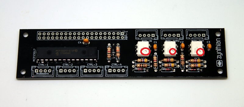
Following photos have to be re-shot for the wiki: http://wiki.zynthian.org/index.php/File:IMG_1252.JPG http://wiki.zynthian.org/index.php/File:IMG_1277.JPG
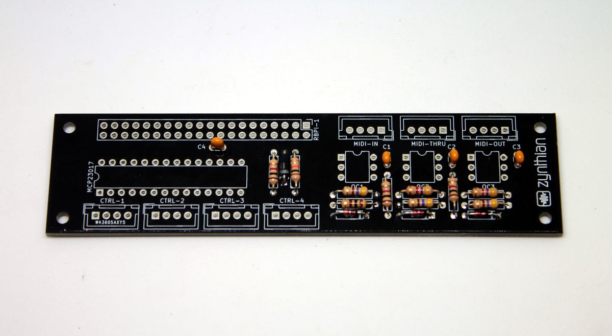
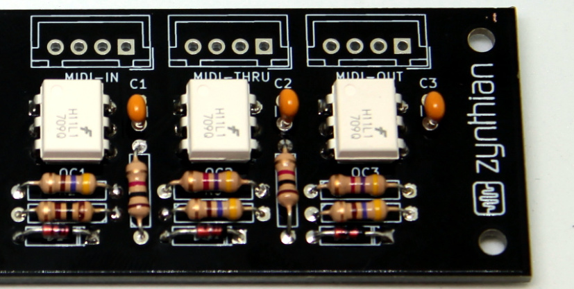
maybe following, too http://wiki.zynthian.org/index.php/File:IMG_1356.JPG http://wiki.zynthian.org/index.php/File:IMG_1474.JPG
The problem is the imprint on the optocoupler chips and with poor contrast you might solder them in the false direction.
Pin1 must show to the 4-pin JST header, not to the resistors.
If someone solders them turned down, MIDI IN and MIDI THRU will lit permanently.
They usually shall lit only if signal is received.
Hi @mj_prod!
The orientation of optocouplers in the wiki’s photos is absolutly correct. Please verify your AIO circuit, because you may be wrong about It. The circuit wont work if you place the ICs rotated.
A photo from your AIO circuit would help to clarify the missunderstanding…
Hello @jofemodo,
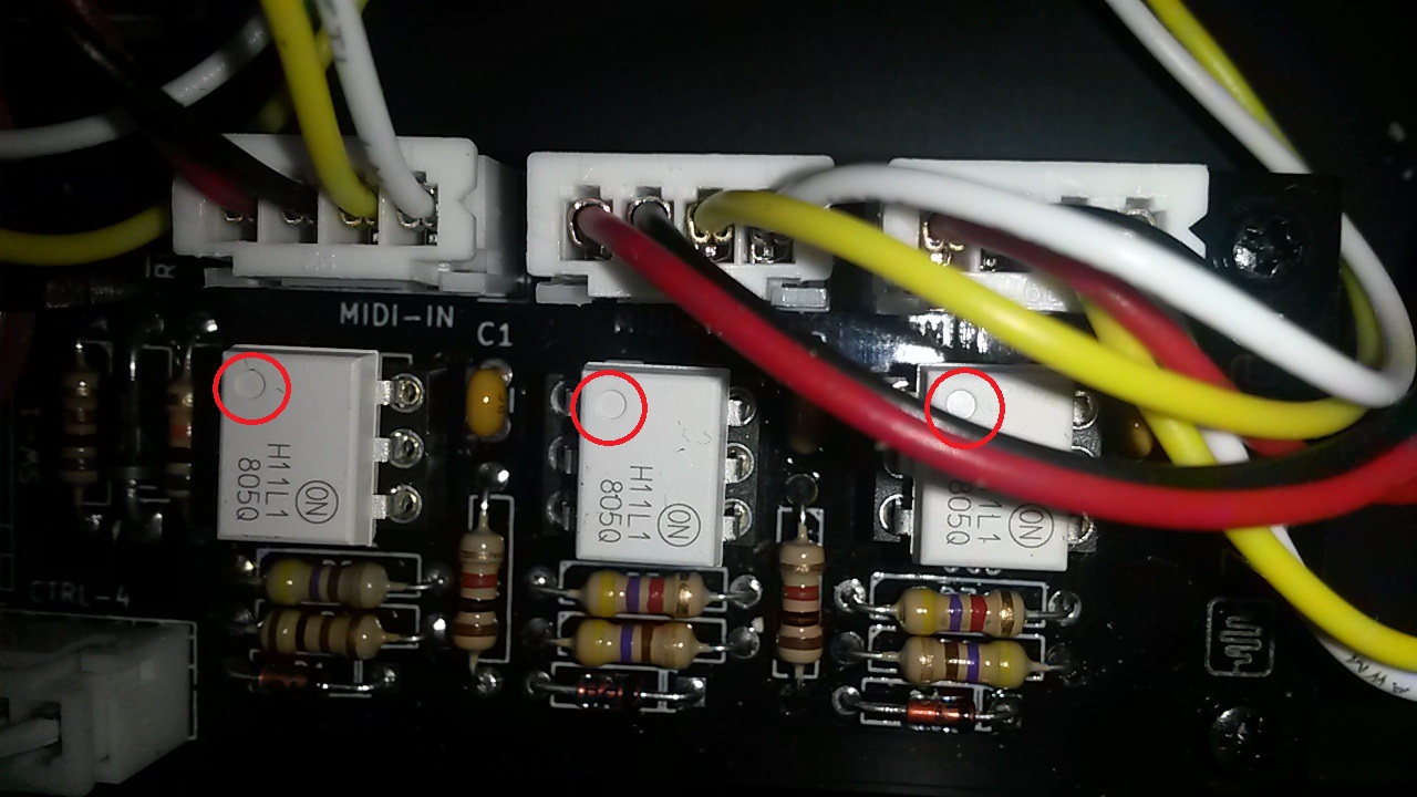
according to the not yet soldered PCB shown in the wiki solder pin 1 is marked with a rectangle. This is where the dot of the H11L1 optocouplers has to be orientated to like shown in my photo.
If they are orientated like this, the MIDI In lits if data is received. If I turn around the MIDI IN optocoupler like shown in the wiki, no data is received, although the corresponding LED blinks if MIDI signal is present.
Luckily, I soldered some sockets for all ICs, even the 28 pin…
Someone who is experienced will go for the orientation that is printed on the PCB, but someone who might look more at the photos than the PCB might get the soldering job done wrong.
I am very sorry to come with this thread and the photos now because it might have affected a lot of people who built their own kit as I did.
All admins and pürogrammers, you did a tremendously well job because I think Zynthian can compete and complete a poor keyboarder’s rig not for cheap, but for ease of operating.
every electronic circuit in a DIL package has an orientation.
I may cite from wikipedia:
As shown in the diagram, leads are numbered consecutively from Pin 1. When the identifying notch in the package is at the top, Pin 1 is the top left corner of the device. Sometimes Pin 1 is identified with an indent or paint dot mark
the PCB shows a drawing frame in white around the DIP chips.
When Pin1 for the GPIO-expander MCP23017 is marked with a small solder rectangle saying the mark on the chip must point to the left, the H11L1 have to point towards the 4-pin MIDI headers.above.
I shot the photo of my zynthian in the same orientation as the wiki pictures were, as you might have seen.
I am sorry to be a bit resistant here. I don’t want to offend anyone writing this.
If I put the optocouplers that way all MIDI LEDs lit bright and flicker if signal is coming in; but nevertheless I get no signal into Zynthian.
If I rotate them 180 degrees so that the dot is upwards,they just lit if signal is coming and I can capture it with the MIDI recorder and if I play it back the captured MIDI events go through MIDI Out so I can see them via MIDI-OX in my Win7-PC.
I didn’t want to get this conversation too technical, but if you turn around the Schmitt-Trigger and the diode side of the optocoupler you canot get signal into the GPIO-Expander.
The Zynthian box is one of the first bigger projects that came along to me.
When I finished to become a radio electronics technician (“Kommunikationselektroniker”) it was 1997…
Maybe someone can show me a photo of their funcioning all-in-one-board V2…
Your optocoupler are perfectly placed. Also the optocouplers in the wiki’s photos!! Both are placed OK because all of them are placed with the right orientation, with the “dot” oriented “upwards”, near the JST connectors. Please, don’t be confused by the serigraphy in the IC’s surface, the important thing is the “mark” or “dot”. In both cases (your photos and the wiki’s photos) the optocouplers are placed with the right orientation.
I have to apologize for the trouble I made.
I have a monitor with a bad calibration. So these pictures had always less (or not enough) contrast for my eyes.
Without any reason I held the writing “f” on the white optocoupler shown in the wiki for the Pin1 mark of it so I put them turned down on my board first…
I am sorry for so much traffic but simultaneous ignoring the hints that @mheidt gave me.
I hope it is all sorted out but if you want to build your module with the photos, @mheidt’s tip is to look at the photos with the highest resolution possible.
Thanks, Marius
optocouplers are sort of dumb parts and forgiving if mounted wrong. Imagine a not-so-easy-to-get IC for some parts of the earth or a project that has two 28 pin ICs and you have soldered one at the wrong place.
Take care and look twice. Staring twice at the same awful monitor life doesn’t become easier. It’s time for me to swap them as well asI think this thread may be closed.
I wouldn’t worry.
There isn’t too much of a protocol for trashing threads and it’s probably your call anyway as you started it. We do of course have the BDFZ who may well spiral in like a hungry condor and tear the thread limb from limb but if we were working on that basis I’d probably have about half of what I type chucked into /dev/null …
I once burnt the letters CA3130 into the pad of a finger when I put the aforementioned chip ( A sample & Hold for an analog synth…) in backwards. The get VERY warm when reversed. Amazingly it still worked for several years after that . …


