Hello everybody
Excuse me for the low-level question, I’m not expert with RPI custom wirings.
I’m trying to build a custom V4 kit, since V5 is out of scope for me at the moment.
I decided to get an HDMI TFT Touchsreen, so I need to wire my encoders and buttons.
My question is: since Hifiberry is a hat, can I wire something on GPIO on top of it?
Wasn’t it dangerous for hat boards?
I saw there are two arrays of holes:
the first, close to the border, is wired with the raspberry from bottom side and pins get slightly up the board
the second is an array of holes with no pins, parallel to the first
My wirings has to go to the first or second array?
There isn’t any problem wiring onto the gpio pins as long as you are careful with a soldering iron and don’t short the pins. The big risk is letting 5v get into the rest of the pins. I’ve been mucking around like this and haven’t managed to blow up a pi but it’s wise to be aware of the risks.
However I would suggest you use a zynaptik board to connect the encoders and s1 to s4 switches. You can use the GPIO pins but they are changed occasionally by the pi gods and it’s a bit of a pig to test and debug.
If you are needing to go ahead this way then the details are available on this form, search GPIO, and ask questions of the likes of me, but remember this area has received some pretty heavy alteration in the pi5 which is holding back zynthian on pi5 so it’s unlikely to move forward…
Depending on just how limited your resources are, I built a set of V4 controls using a Teensy and some cheap parts from aliexpress. I do not know how well I actually documented the pin wiring, but it can be reconstructed from the code, and if ordering some rotary encoders and switches and a $30 or so Teensy is on the table for you, I’d be very happy to help you put them all together. The Teensy code is here:
(edit: to be clear, the Teensy acts as a USB midi controller that you then plug into the zynthian - as I recall I still have one tiny quirk to sort out, which is that when you reverse direction on the rotaries, it doesn’t see the first “click” for some reason…)
You would also need to get a touchscreen, I have a couple of Waveshare 7" thingies, also from aliexpress. It’s all gonna be my backup zynthian unit just in case my main one decides to cack onstage (has never happened, it’s astonishingly stable…).
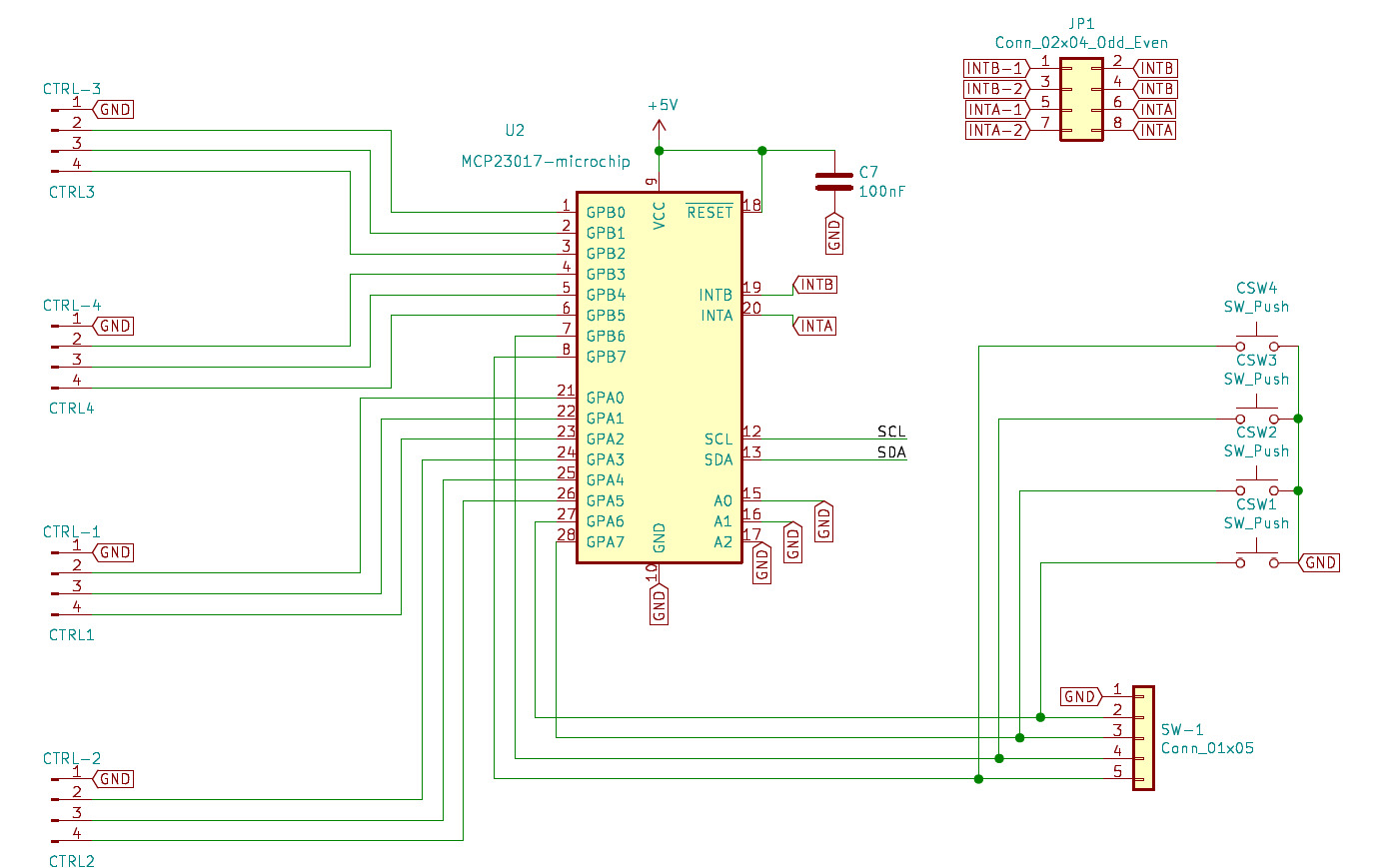
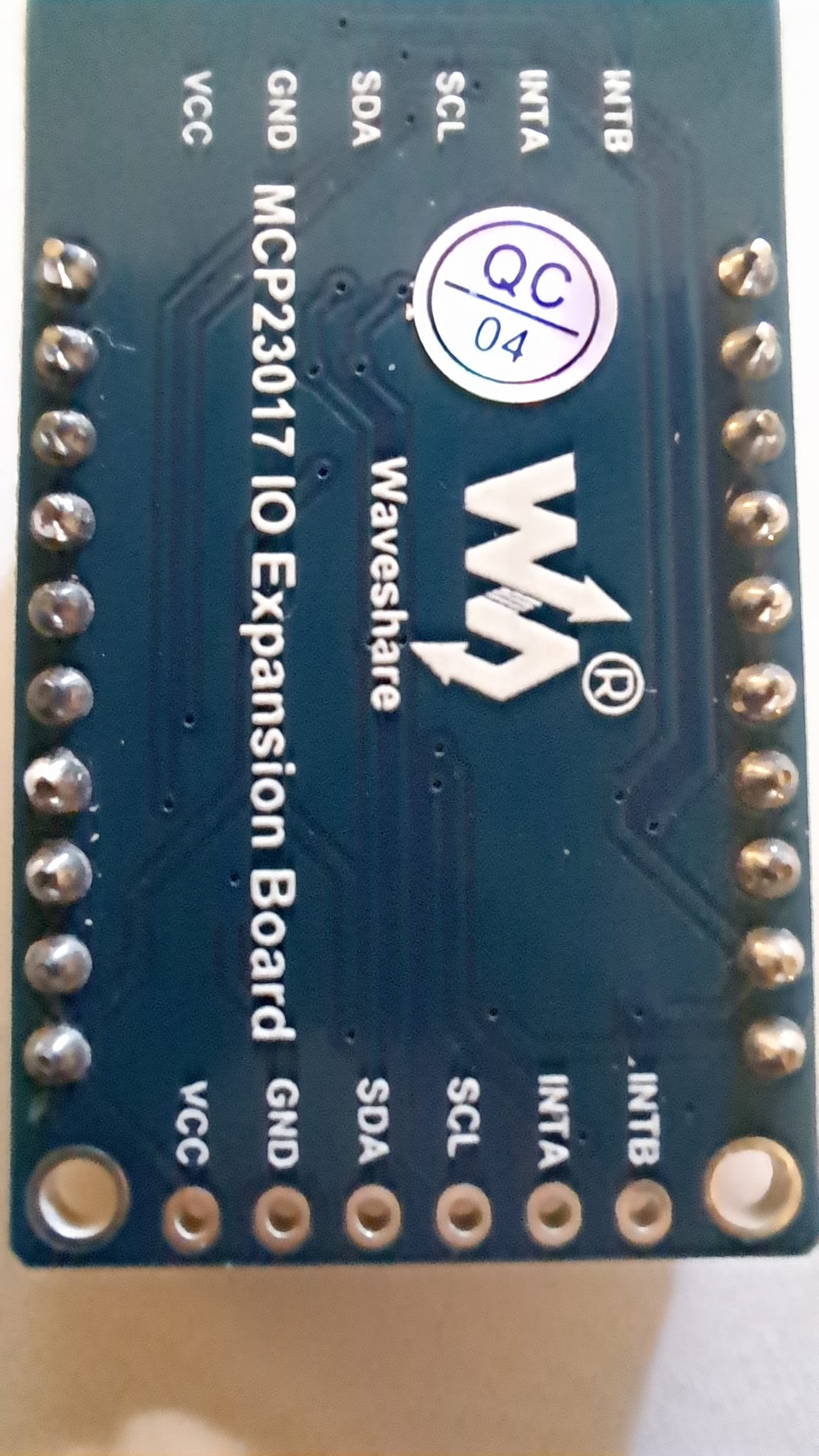
A mcp23017 breakout board as can be found on aliexpress or Amazon will be cheaper then the teensy and will stick to the Zynthian original design. With a second one you’ll even be able to mimic v5.
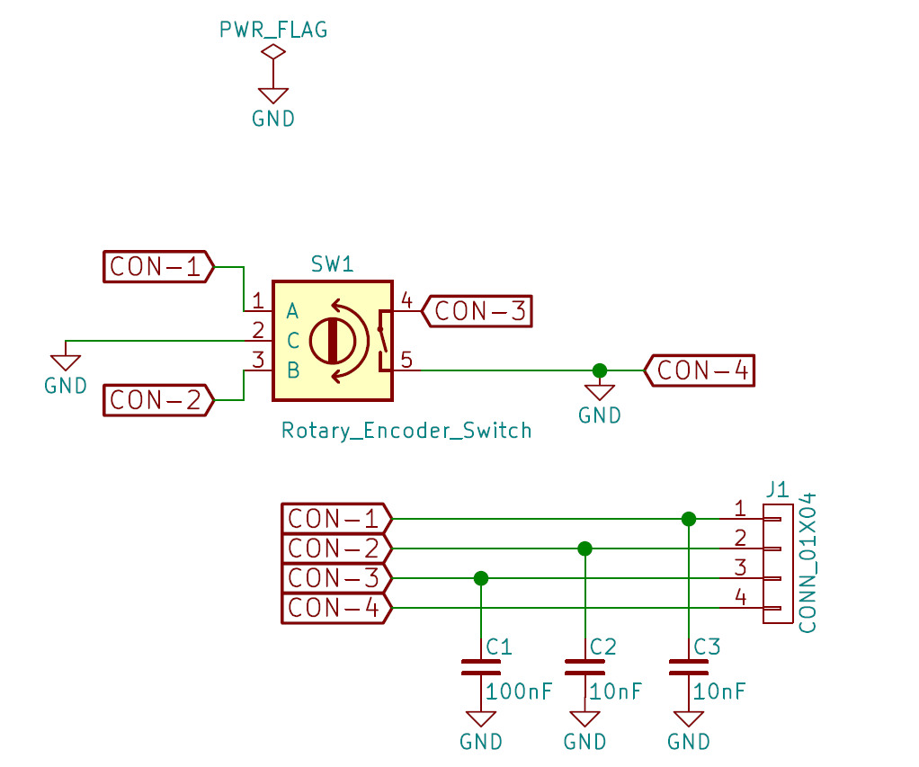
I’m checking the wiring scheme for the encoders, but it seems strange to me.
In the scheme, pin 1 of J1 is directly connected to pin 1 of the encoder and with C3 that, on the opposite side, is connected to GND.
Where should i connect GND? To the metallic case of the encoder?
On the ZynScreen schema I noticed that pin1 of J1 of the encoders is always conncted to GND (I suppose aluminium case).
Thus C3 is placed between GND and GND? Isn’t it unneeded?
Ground is connected to the centre pin on the encoder, between the A & B pins. if you have encoder boards that mention +V or similar ( they are normally mounted on little PCBS) then they need attention to make them work…
The MC23017 has pull up resistors inside it which will pull the appropriate pin up to the positive voltage inside the chip which it the pin isn’t connected to anything will register as a 1. When the individual encoder A and B wires are connected to the centre pin, which they are as the encoder is turned then they are connected to OV and this registers as a 0 in the chip. The A & B pins in the encoder have a clever sequence of on’s and offs as they rotate and this can be interpreted by the Zynthian software as turning left or right…
This is worth of a look to get the idea. Encoders.
An encoder that has a wiring fault or is only connected on one side tends to move a little on the screen but not change it’s position…
The capacitor is there for debounce. I’ve not used them myself on my various builds but they probably do improve performance, especially in noisy electronic environments, but I would focus on them too much. Connecting the case of the encoder to 0V probably also helps the noise characteristics.
In this other schematic I see that CON-4 is connected to a PIN of MCP23017, whilst GND is connected to CON-1.
Putting those pictures together it seems to me that:
since CON-1 is connected to GND from ZynScreen board, C3 is placed between GND and GND
since CON-4 is connected to a MCP23017 pin (depending on the encoder number):
either I have to connect GND to CON-4 (taking it from somewhere else, but I don’t know from where) connecting all CON-4 pins to GND, thus connecting them all together
or I barely connect CON-4 tio those 2 pins ignoring the GND note
Maybe I’m looking at a wrong couple of schematics (e.g. controller of a version and ZynScreen of another one)
I think you might be looking at connections to the small PCB’s that zynthian used on encoders.
The capacitors are placed between the active pins that change their state as the switch or encoder is activated and ground.
As I say, leave them out initially if you want, Then if there seems to be noise them add them afterwards. They want to be near the device that’s switching so you can simply solder them across the encoder pins from A to centre pin & B to centre pin and then just across the encoder switch.
I’ve got four or five zynths here and only the ones that use the zynaptik board have the capacitors on and they all work. Give it a go that way so you can, at least, discover if the encoders do control the GUI…
Hello
Currently I fixes SW issues, so it’s time for me to switch to HW part.
Do you know if there are Y-connectors for GPIO bus?
This could allow me to put my HW either before or after the HifiBerry without having to solder directly on the HifiBerry pins.
Thanks
This can be one of those decisions that become obvious later.
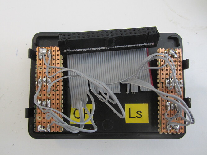
If your audio hat (card) doesn’t have pins on the top side then you do have a bit of a problem if you want to have any degree of flexibility with the construction.
Things like this may help you…
It could go beneath your audio card and still provide access to the GPIO pins.
I used an old disk drive cable but this isn’t an option if your audio doesn’t have the pins on it’s top side…
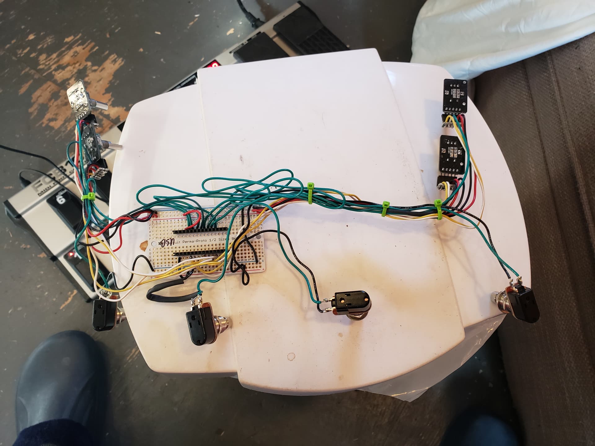
Now, based on your previous suggestions, for connecting control1 to the board I think I should have to connect:
GND to the middle pin (pin 2 of the rotary encoder)
GND to the lower pin of the switch (pin 5 of the rotary encoder), that will also be connected to GPA2 on MCP23017
the upper pin of the switch (pin 4 of the rotary encoder) will be connected to GPA1 on MCP23017
how should I connect pin 1 (A on the rotary encoder) and pin 3 (B on the rotary encoder) to MCP23017? From the scheme I suppose that pin 1 is connected to GND, pin 3 is connected to GPA0 , but from your previous post I’m not shure about it
Ultimately you need to make sure that the switch operates the switch GPIO pin and the two encoder connection A& B are connected to the other two GPIO pins for that controller.