Hi all! Just built my V4 zynthian, and all went pretty smoothly. I ordered V4 parts (except for the hifiberry, ordered it from their website since it was out of stock at the zynthian store). Got to the software update, then tested the encoders and it turns out that the upper right encoder registers pushes but will only make the values change +/- 1. So, if the default value is 64, I can only make it 63 or 64. Swapped cables and it remained the same, it seems to be the encoder and not the cable.
I did have to solder the pins on the hifiberry, but I guess this shouldn’t be the problem right?
EDIT: turns out when I swap encoders the hardware is fine, it’s just the encoder plugged into the top-right that will always misbehave… Could it be the connector on the screen?
There is something not quite right in the connection of the upper right.(L/S?)
Have you a multimeter?
Shouldn’t be. Can you confirm you have a proper stereo image on the output?
So make a noise in just the left channel, does it come out on the left the right or both?
Then do the same on the right channel.
That will tell you if the audio side of the card is behaving itself.
If you are using a kit then the controls all come in via 12C from the onboard chip so if you muck up the i/O pins of the zynth with a bit of robust soldering nothing will work.
Of course if you can do that much, the loss of l/S encoder doesn’t prevent
But actually, when I used the problematic encoder in place of another one, it worked fine. So the encoder itself seems to be alright… I do have a multimeter, let me know if there is anything else I can check
You need to see what the 23017 is actually seeing on it’s pins. but if you can ensure that there is continuity from somewhere on an encoder board to the relevant pins on the chip ( pin 2& 3 I think but check for yourself). Also check for shorts to ground on these pins or any connection to pins around and each other.
Lastly try turning the encoders and see if there is any response on the pin. There’s no external pull up resistors to worry about. I find a quick check is to set my meter to continuity and put it on the two pins on the chip. When you turn the encoder you should hear it connect and disconnect, cos at one point in the rotation both encoders are connected to OV.
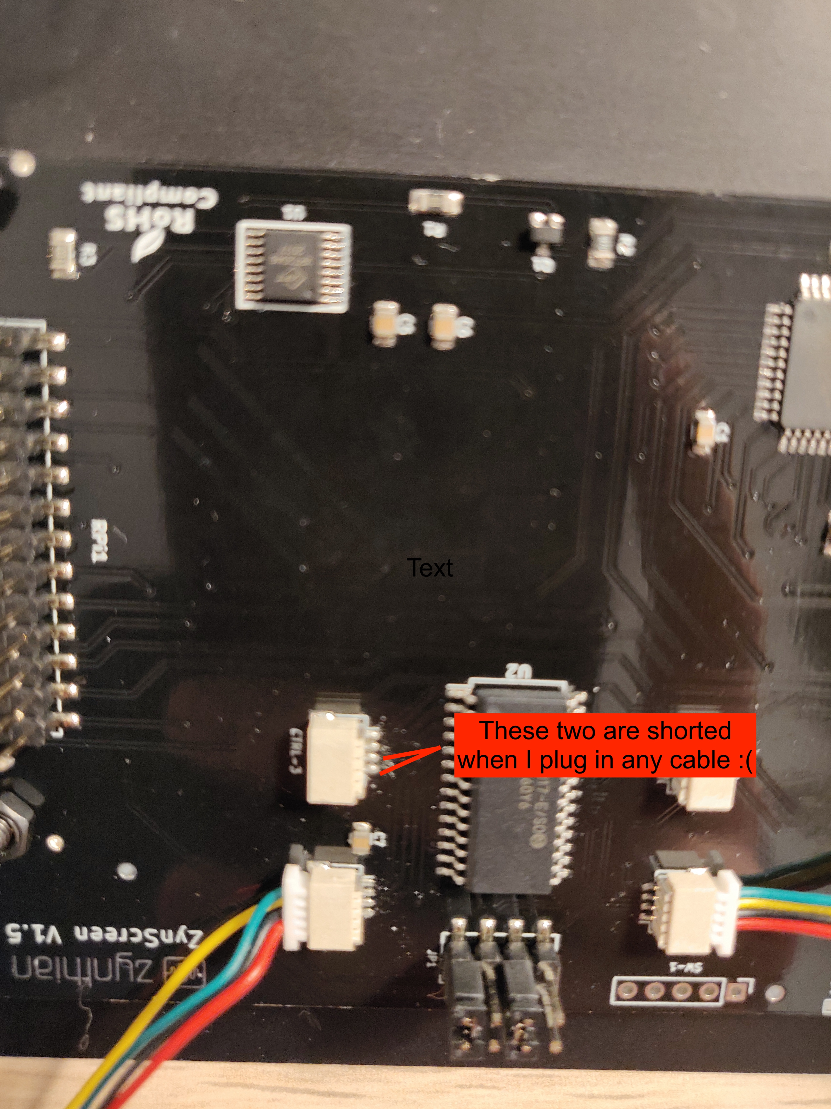
Okay, I think I found the problem with the multimeter! On the screen socket of the problematic encoder (no matter which of the 4 encoders or 4 cables I put there) two pins are shorted, and they connect to the left pin on the row of 3 in the encoder (the non square one that is not ground). I attach a picture for reference.
If I don’t plug a cable, they are not shorted though.
Did you force the display connector when plugged the harness?
Could you check the pins inside the connector to see if they are bended In such a case, you could try to fix it …
If the problem is on the soldering, then it’s clear that it’s a manufactoring problem and i would send you a new display ASAP.
Good catch! I did see a bent pin, now I fixed it with some tweezers and the encoder passes the continuity test will now assemble, power up and test, but it looks like probably that was it thank you so much for your quick help!


 will now assemble, power up and test, but it looks like probably that was it