Pisound hardware button gpio integration

Hi,

I am toying with a Raspberry PI 4B + Blokas Pisound on latest vangelis.

Since it has a hardware button, it would be a shame to waste it. It’s available via GPIO 17.

The hardware is working: below is the off and pushed state, respectively.

(venv) root@pisound:~# pinctrl get 17
17: ip pu | hi // GPIO17 = input
(venv) root@pisound:~# pinctrl get 17
17: ip pu | lo // GPIO17 = input

Next I tried configuring it like this. Tested after a reboot but I don’t see any logging nor effect.

Any hints or better ways to get this working?

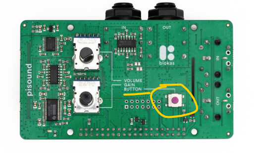
Note I am using ‘just’ the out of the box Pi + Pisound hat without extra hardware, and just the Zynthian OS vangelis without the custom button scripts that Blokas provides.

1 Like

Hi Zynthians,

Any hints on how to proceed troubleshooting this?

Regards

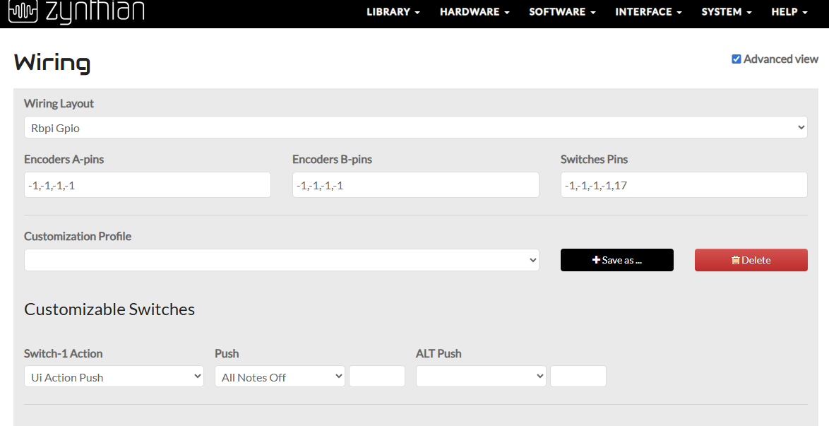
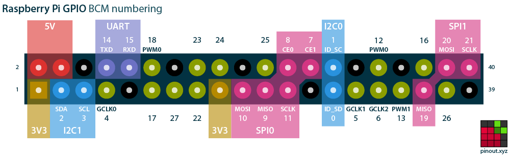
Might be worth seeing if a temporary soldered GPIO17 connection, but I would check the mapping because the GPIO pins on the Pi do not directly relate to the settings in the zynconf interface which are BCM based.

Image from https://pinout.xyz/

Interesting.

Also found this meanwhile, unfortunately it does not mention the button (source General - Pisound Documentation)

Raspberry Pi Pins Used by Pisound

pinout map rev3

  • Black - Power supply pins.

  • Red - Pins used by Pisound.

  • Green - Pins available for your use.

  • Blue - Pins reserved for Raspberry Pi hats use.

Pinout of Pisound Header

pisound-header

Number Corresponding Raspberry Pi Pin
1 Ground
2 5 V Power
3 BCM 7 (CE1)
4 3v3 Power
5 BCM 5
6 BCM 6
7 BCM 22
8 BCM 23
9 BCM 27
10 BCM 4 (GPCLK0)
11 BCM 15 (RXD)
12 BCM 14 (TXD)
13 BCM 2 (SDA)
14 BCM 3 (SLC)

Curious: does the the pinctrl command in my original post give a hint as to what needs to be configured?

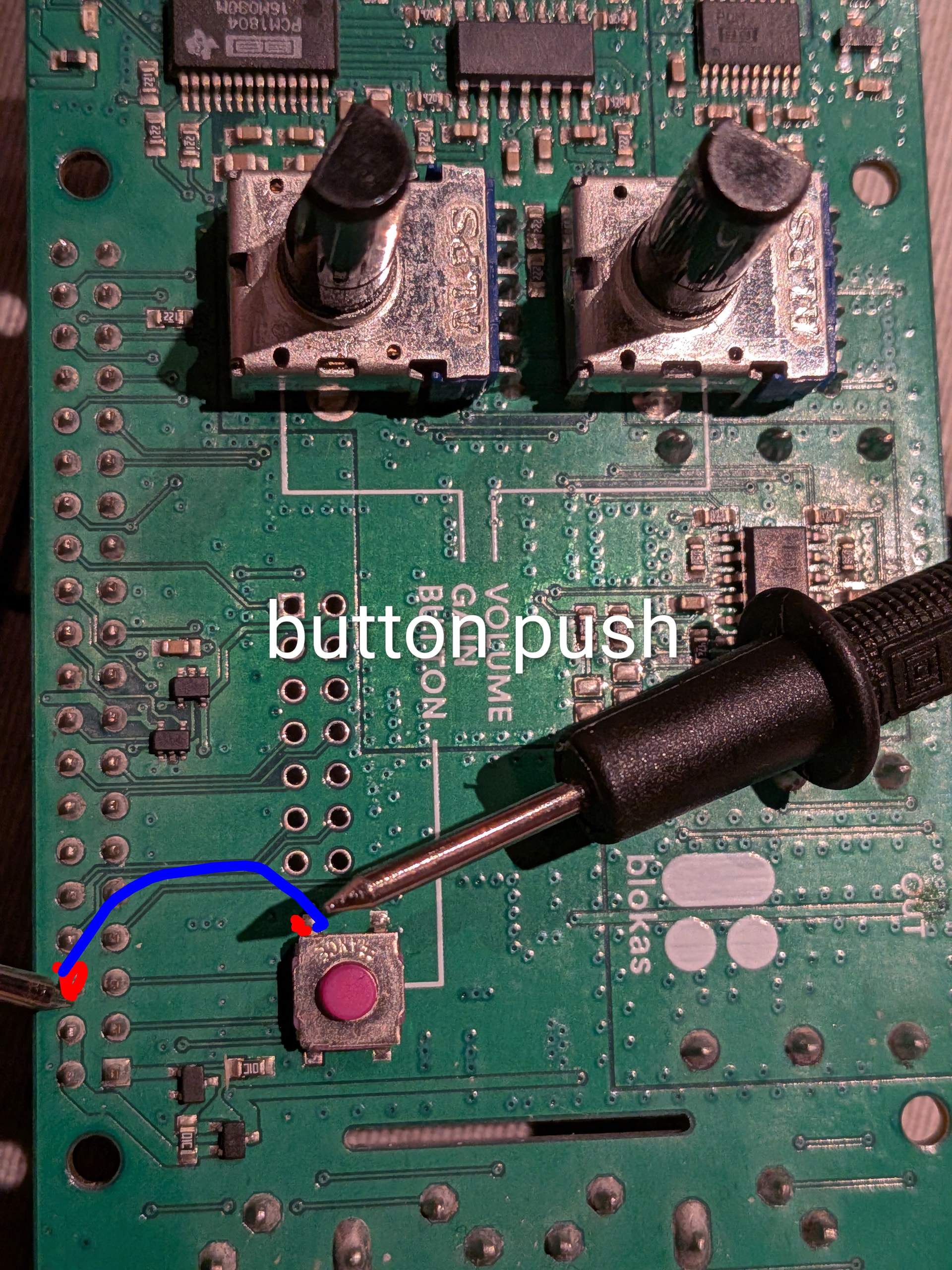
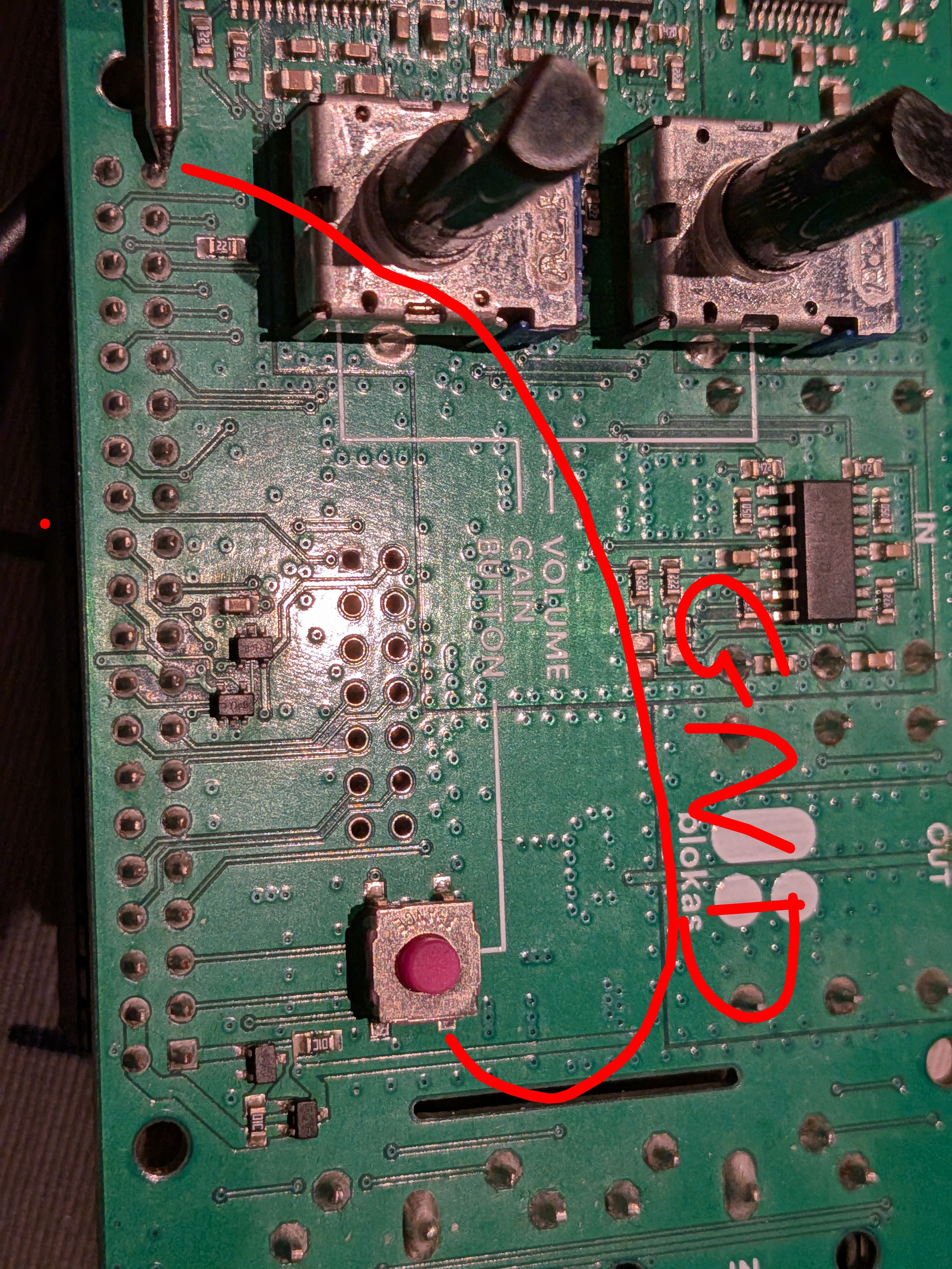
You are probably best to disconnect the card from the edge connector and put a multimeter connected to 0V pin on the edge cnnector and then go hunting for the appropriate pin on the edge connector whilst repeatably pressing the button to see which pin it’s actually connected to.

I was taught that electrons don’t read and can’t identify wire colours so the only real way to be sure is a multimeter.

The secret with this sort of endeavour is make sure the device is securely mounted and you are comfortably able to access the pins with the multimeter probe without the probe leads moving the circuit board whilst you frantically grab for the meter itself as it falls off the table at the same time….

You get the picture.

Once you know which pin you are talking to it should be reasonably painless from there. . .

1 Like

Here are the results of the jury :wink:

So assuming the square pin marks pin one. That’ GND on pin 39…

Which is as per Datasheet.

And pin 6 for the GPIO pin. Which ‘might’ be BCM 6 in the zynconf world.
Which doesn’t feature on the pic I supplied.

Such is the wonderful world of mappings.

It’s probably too late to try for a relabelling in webconf.
The chaos would be outstanding…

Yeah the docs are not really helpful. So should I try configuring value 6 in the the mappings? :crossed_fingers:

Give it a go.

But do as much checking as you can.

You shouldn’t damage anything, and whatever degrees of preparation you might put in place, there will always be a moment when you just have to try it.

1 Like

Did a set first boot on latest vangelis to have a clean starting point.

After setting the soundcard to pisound, configured wiring:

The good, no errors in UI log, the sad also no info or effect when button is pressed.

I also tried with value 17 instead of 6, same result

One thing that improved after reassembled pisound hat:

I can now see button press in the Android app Raspcontroller

The value changed from 0 to 1 when button is pressed.

Gpio is accessed via pinctrl.

So hardware seems to work.

Hmmmmmmm.

I’ve got a keyboard to fix today, so I will get that out of the way.
And think on what might be happening here…

Pictures of the Pisound board attached to the Pi and any other kit connected might be helpful, in the mean time.

No pressure!

In terms of photos, can do but not much to see, no extra hardware beyond the pisound hat directly connected on top of the pi 4.

Meanwhile I dived in the archives and found your helpful post on gpio readall.

A newer replacement is available which works across Pi versions.

I used this to snapshot the GPIO state between button off and button on. It shows GPIO17 again.

Output is below:

buttonon (2.0 KB)

buttonoff (2.0 KB)

diff (310 Bytes)

So as far as I understand, this is no different than connecting a button directly to the relevant GPIO pin and ground. My guess is it’s now a config error on my behalf.

Regards

I have a new idea, the dtoverlay=pisound is set by selecting this audio interface. This might have side effects.

I’ll try testing with a dummy Audio interface to see if that makes a difference in terms of detecting the button press.

UPDATE: tested and no improvement with dummy audio device. Still no detection of either GPIO 6 or 17 as configured on earlier post.

I also tried the configuration below, but no difference either.

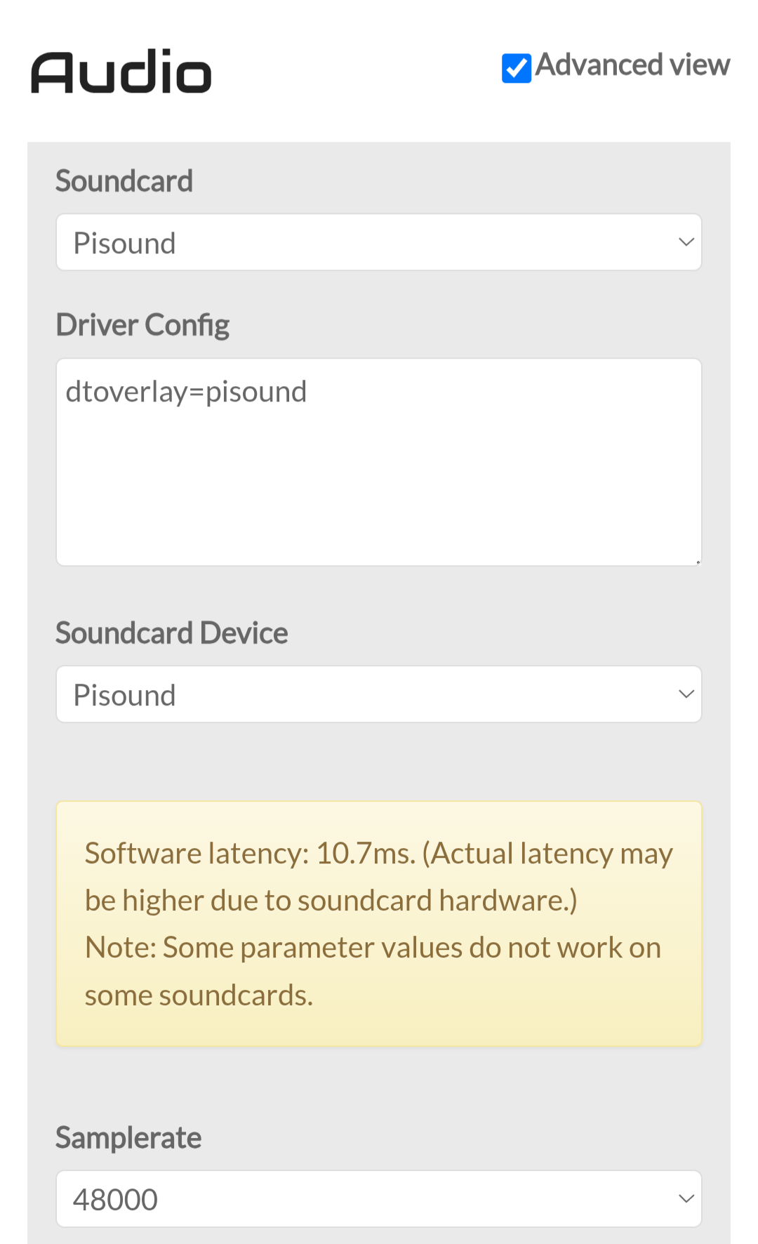
Is this a pure , whatever that means, zynthian install. ? There are no entries in /boot/firmware/config.txt.

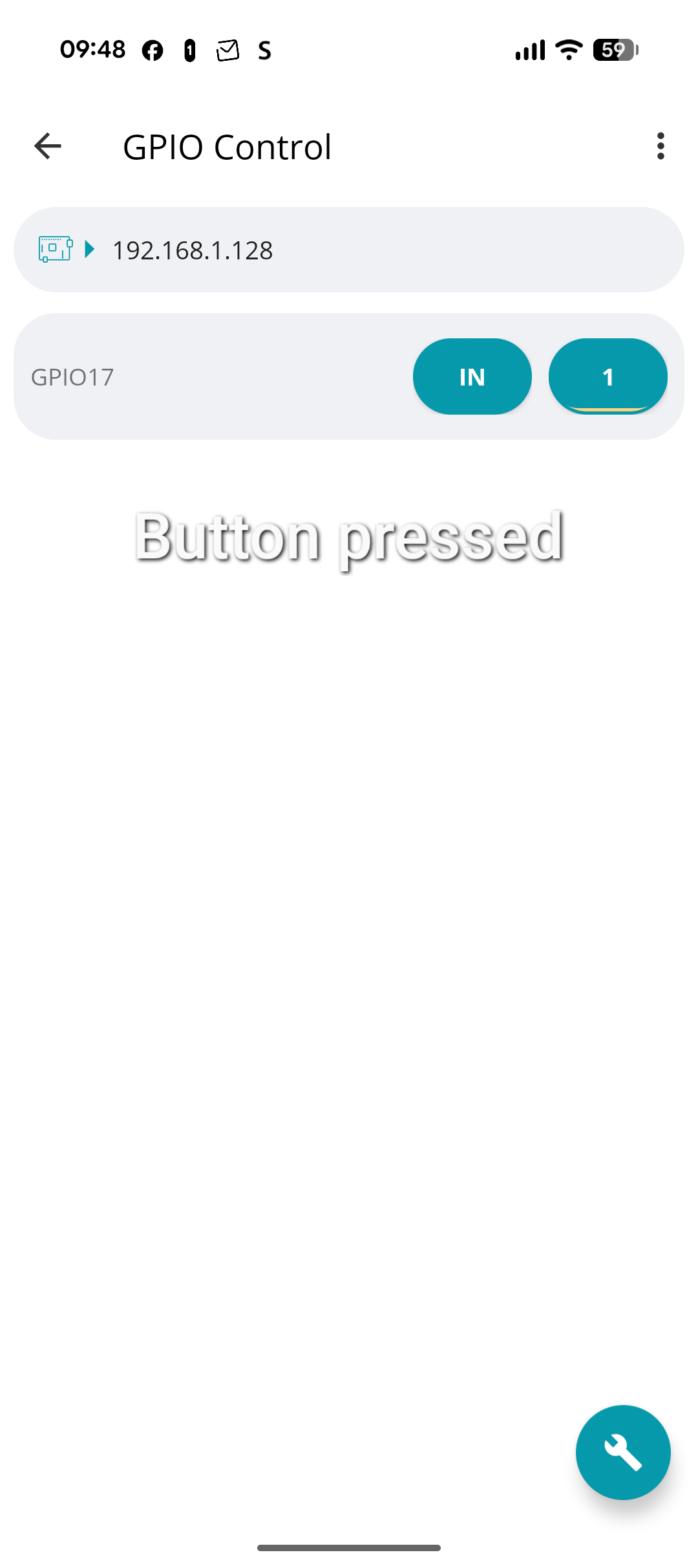
It might be worth connecting the two devices and check the actual pin involved to see if it’s changing as you press the button with both onnected.

You could have a short circuit on one side that presents the 3.3V appearing and dissappearing at the paropriate times.

It’s easy to start believing the pernitious Gods of zynthian extract great joy from our desperate attempts but surely not even they could be so fickle.

There is always a reason and it is very, very rarely personalised,.

Simply electrons going where you don’t expect them to.

config.txt - boot/firmware/config.txt contents when pisound is configured. It contains

dtoverlay=pisound

Due to the Audio card selection below

This is a regular Pi 4 B plus pisound hat on top. Nothing else. Updated to latest vangelis.

I think I’ll first use a different Pi 4 and connect just a button to test the configuration. There are too many moving parts now. No lack of Pis here…

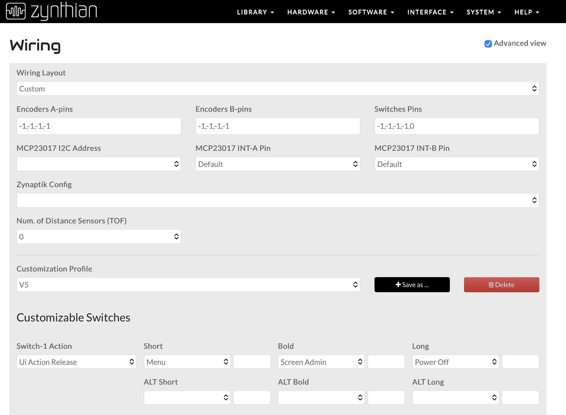
Solved! I tried all possible GPIO on the original Pisound/Pi4 combo. The winner is 0. My original diagnostics must have been wrong. This configuration makes the button work with short, bold, long support.

Regards

3 Likes

Excellent! so which pin was it actually connected to in the end?

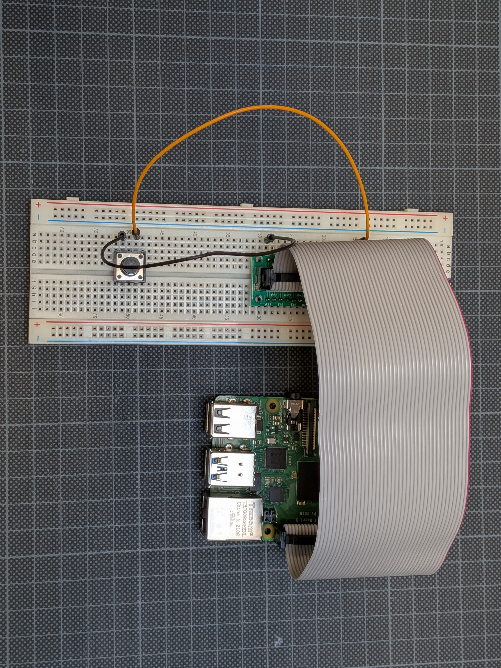
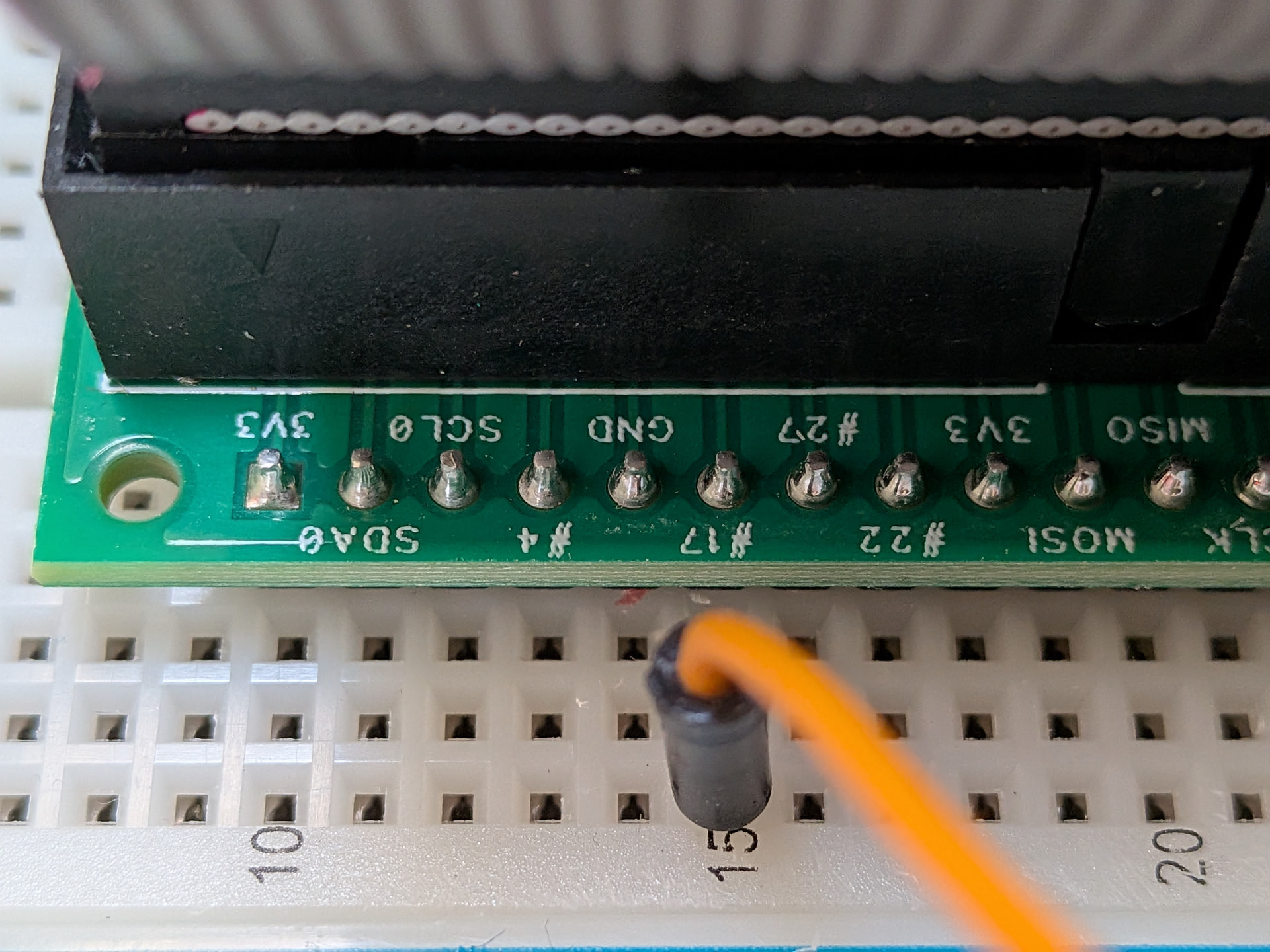
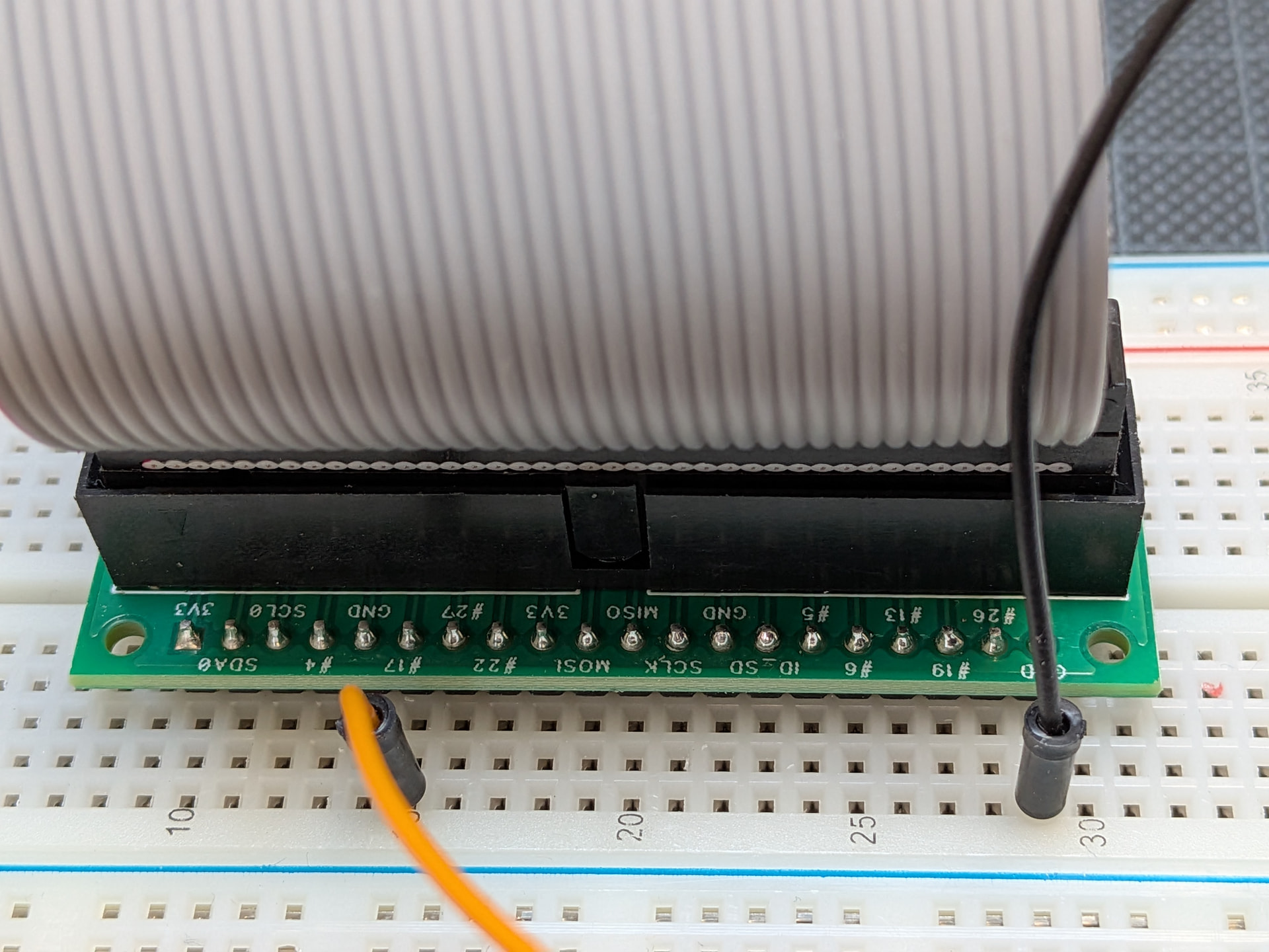
As one of my multimeter leads broke while attempting to test this, I reproduced the working configuration on the stand-alone Pi 4 and a breadboard setup.

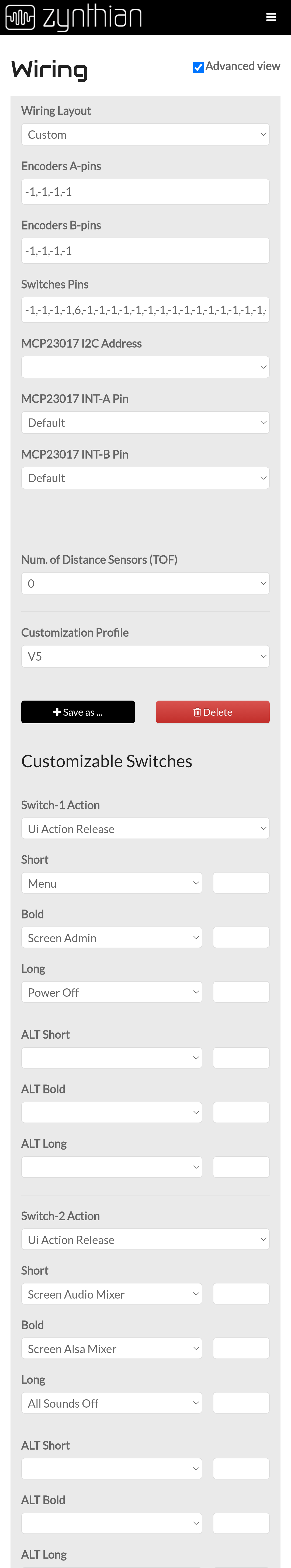
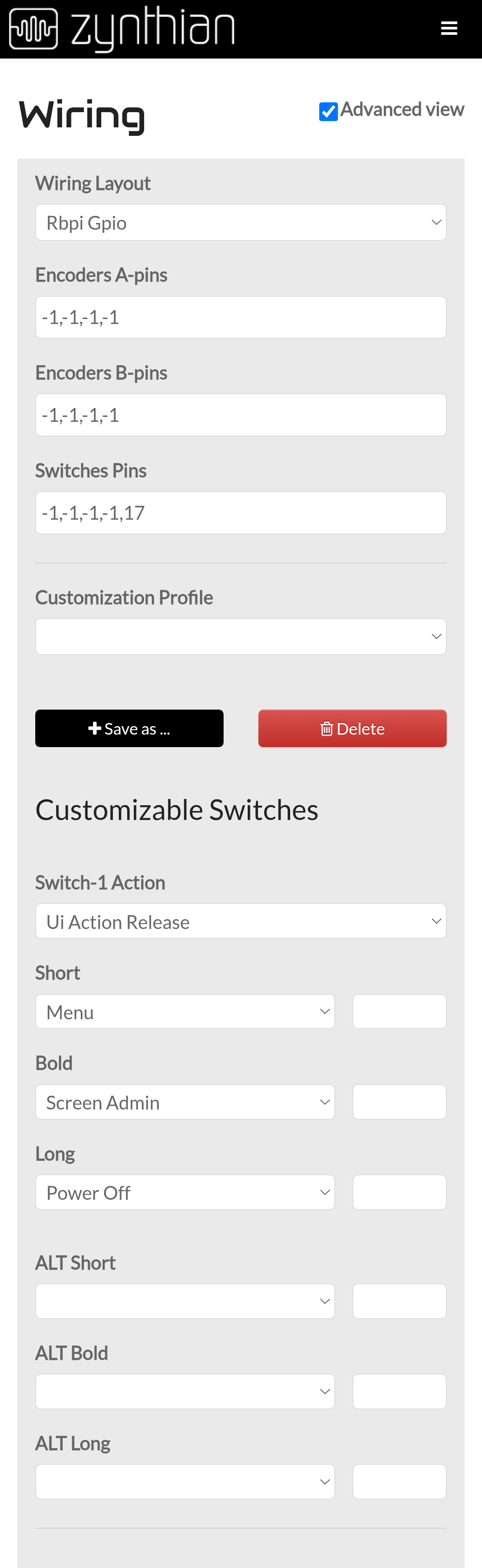
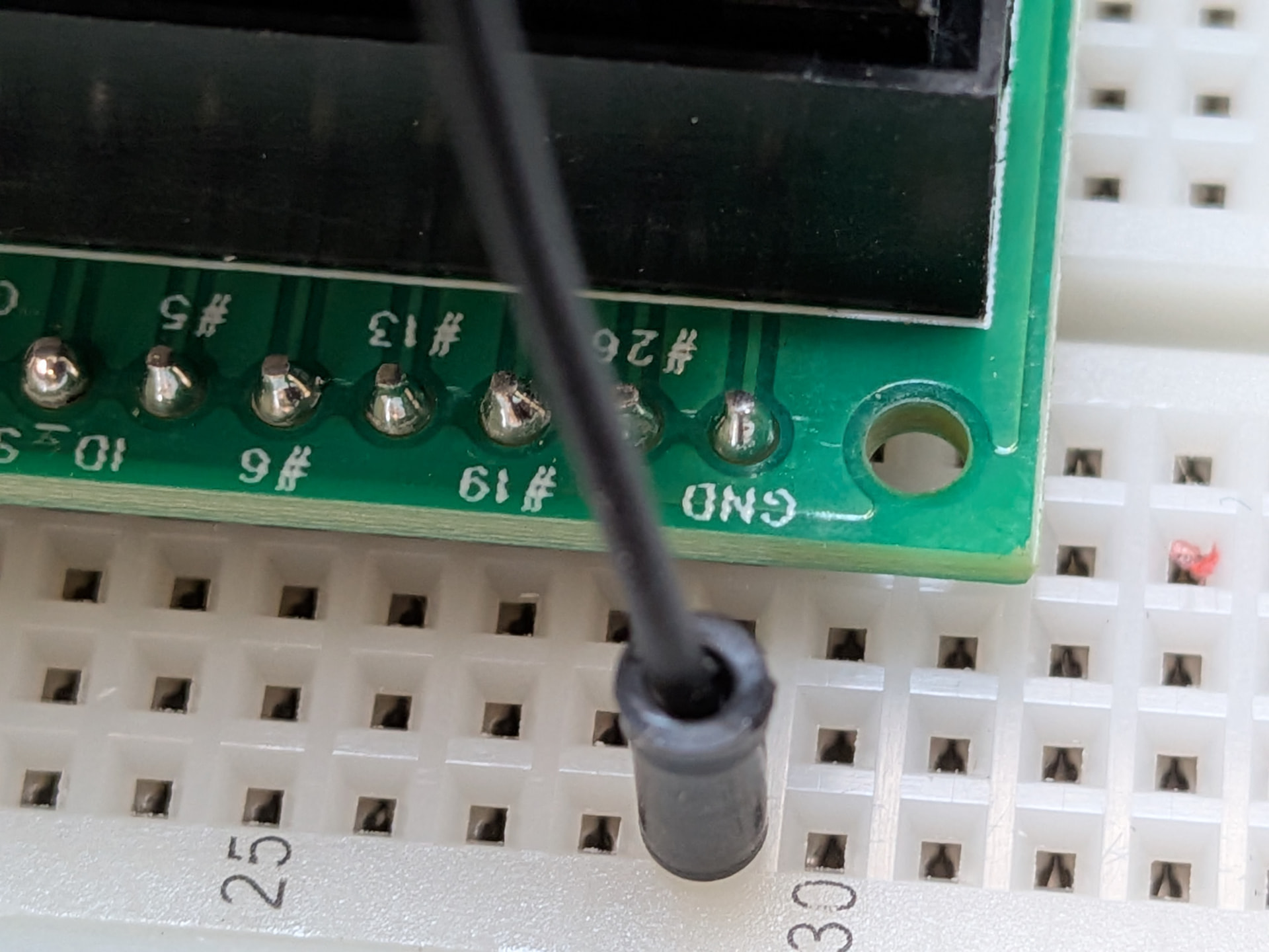
It shows that GPIO 17 … is configured as 0 in webconf (same config as above). As @wyleu has pondered before, the magic of raspberry GPIO numbering schemes.

And behold, the result is a working button:

DEBUG:zynthian_gui.zynswitch_short: Short Switch 4

startx[2306]: DEBUG:zynthian_gui.callable_ui_action: CUIA ‘MENU’ => None

Can you set it up as a one button sooperlooper?

I was wondering about that….

I could configure it to send MIDI, and manually learn in sooperlooper. Unless is there a built-in webconf wiring config that would directly call the single button mode, skipping the need for manual midi learn?