Hi boys!
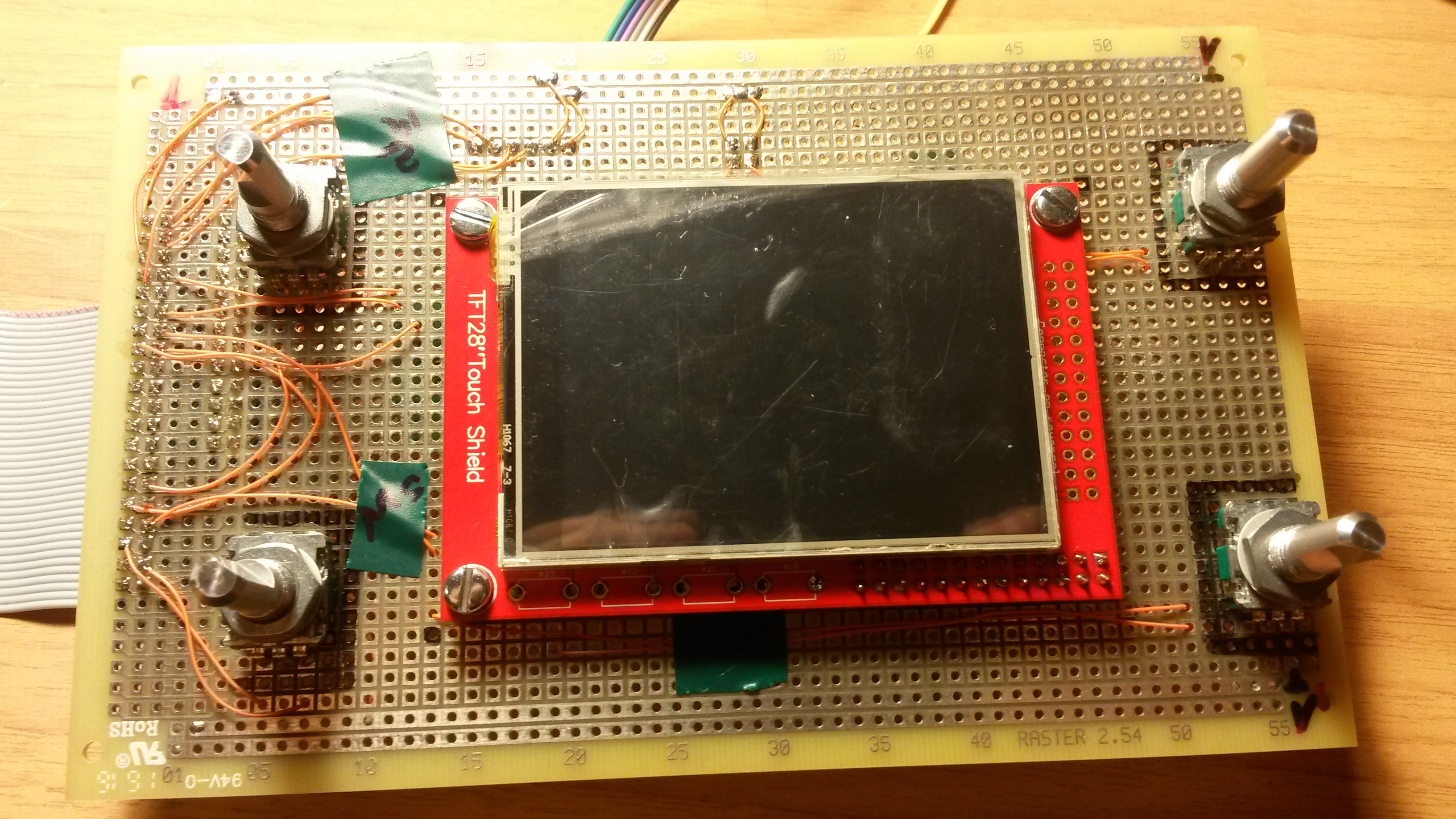
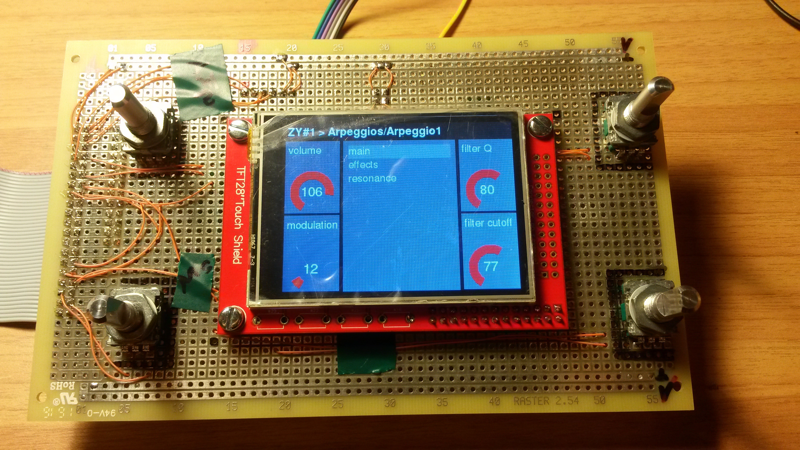
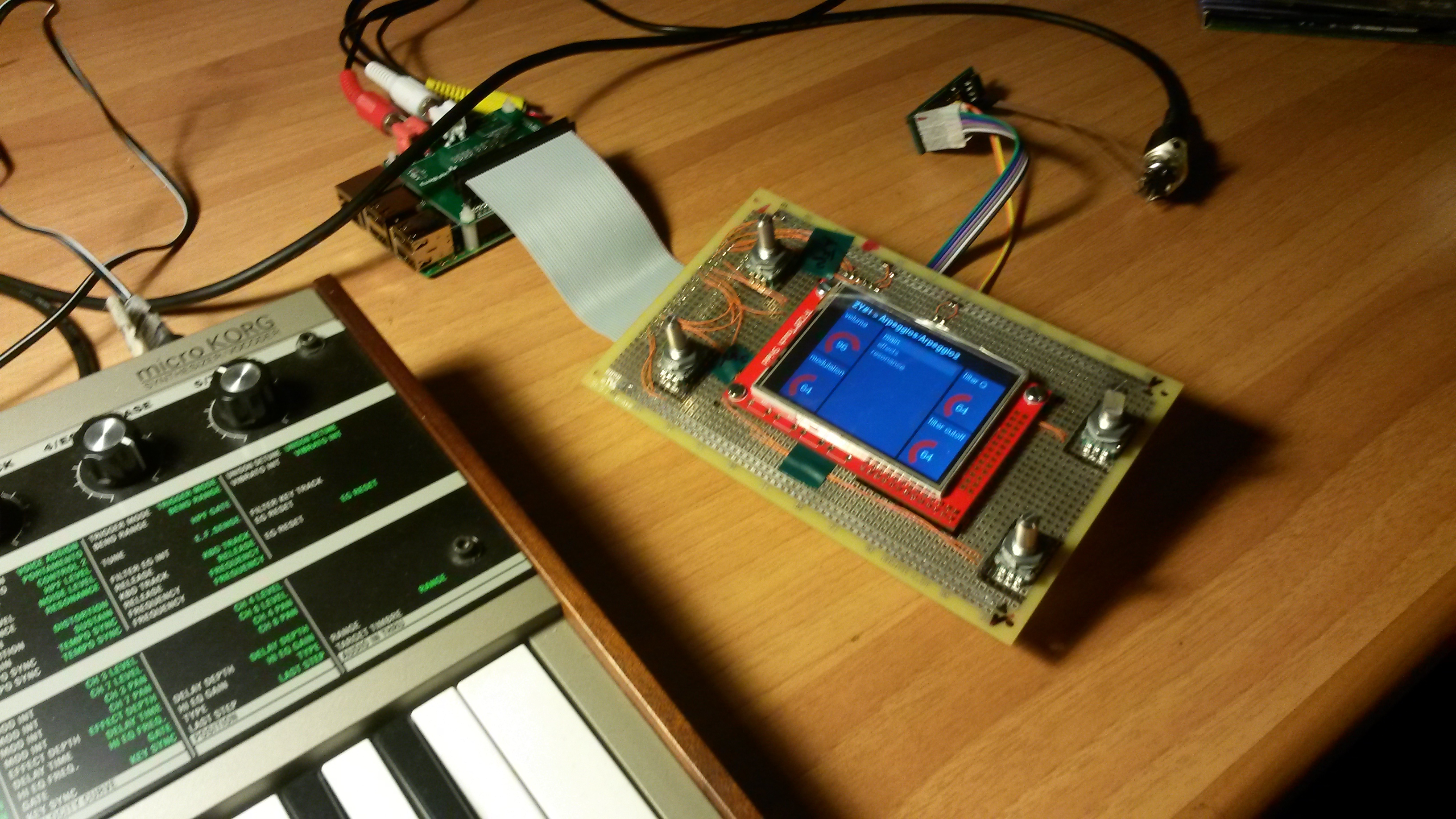
Following the idea of Keeze101 reported in “Success cases” topic I also thinked to use only one board to integrate the four encoders and the display.
This for two main reasons:
In order to have a minor number of “free” cables in the Zynthian box
Hi Marco!
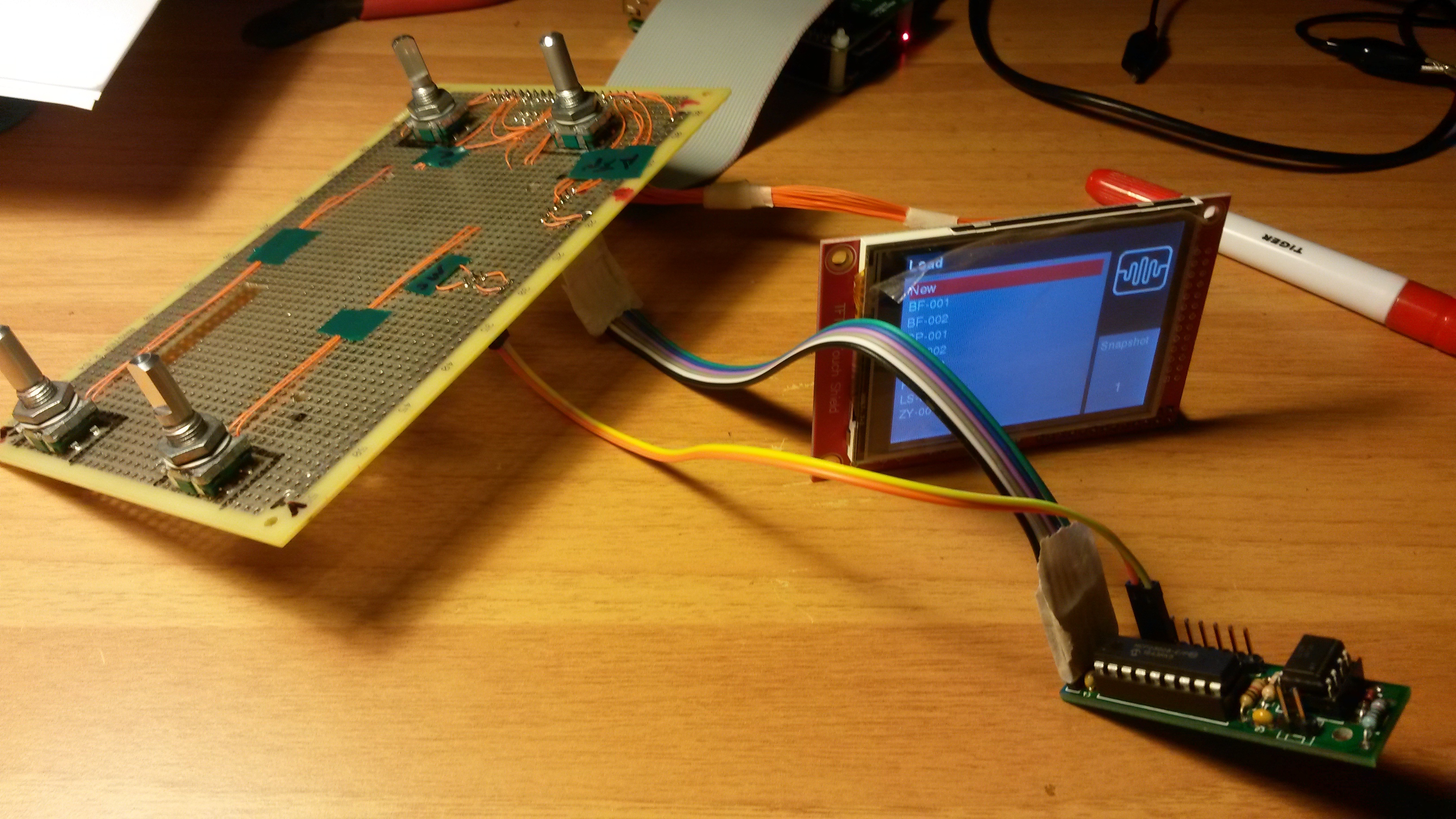
Congratulations! It looks great!! Really great!
A little appointment about capacitors and rebound. Low level software that manage encoders and switches (zyncoder library) ignore spurious rebounds, so you can’t “see” the rebounds althought it happen. Capacitors don’t avoid completely the rebounds, but it reduce the number, so we avoid some IRQ calls that consumes high priority CPU cycles. I think it’s better to put the capacitors.
Another question is: What is the optimal value for those capacitors? I have not studed in deep this question … i used a value that i readed somewhere
HI José!!
Thank you very much for your congratulations, I’m honoured of that!
Ahhhh…now I understand the real reason for the caps! I think I will add them!
In my opoinion looking at the frequency of the rebounds, the value you used should be fine (I also readed somewhere that value…).
Thank you again!!
Great thinking. I made a similar veroboard with the encoders & IO expander for my project.
I made a schematic in Eagle at the same time. It’s an easy task to layout a circuit board from this which I could offer back to the group if there’s an interest. It would take a bit of reviewing to make sure that the encoders are in the right place to fit in the official box.
Dear Andy,thanks for your contribution.
And excuse me for this very late reply… too many work engagements!!
I would like to see your Eagle project!!
Thank you again! !
That Eagle schematic is quite out of date. This was for I was for the single board with IO Expander and 4 encoders that I was building. I made a prototype with veroboard, but gave up because I had horrible mechanical problems. It was very difficult to drill the holes for the encoders and align them to the cutout for the display. Then I discovered that I’d placed the 40 way connector in the wrong place & gave up (after a lot of screaming…)
I’ve learnt from my mistakes & I’m concentrating on my second build. It uses a 5 inch HDMI display. I’ve designed a ‘breakout’ board that plugs to the Raspberry PI with wired connections to the encoders. The board is on it’s way from China. I’ll share details with the group when it’s all tested.