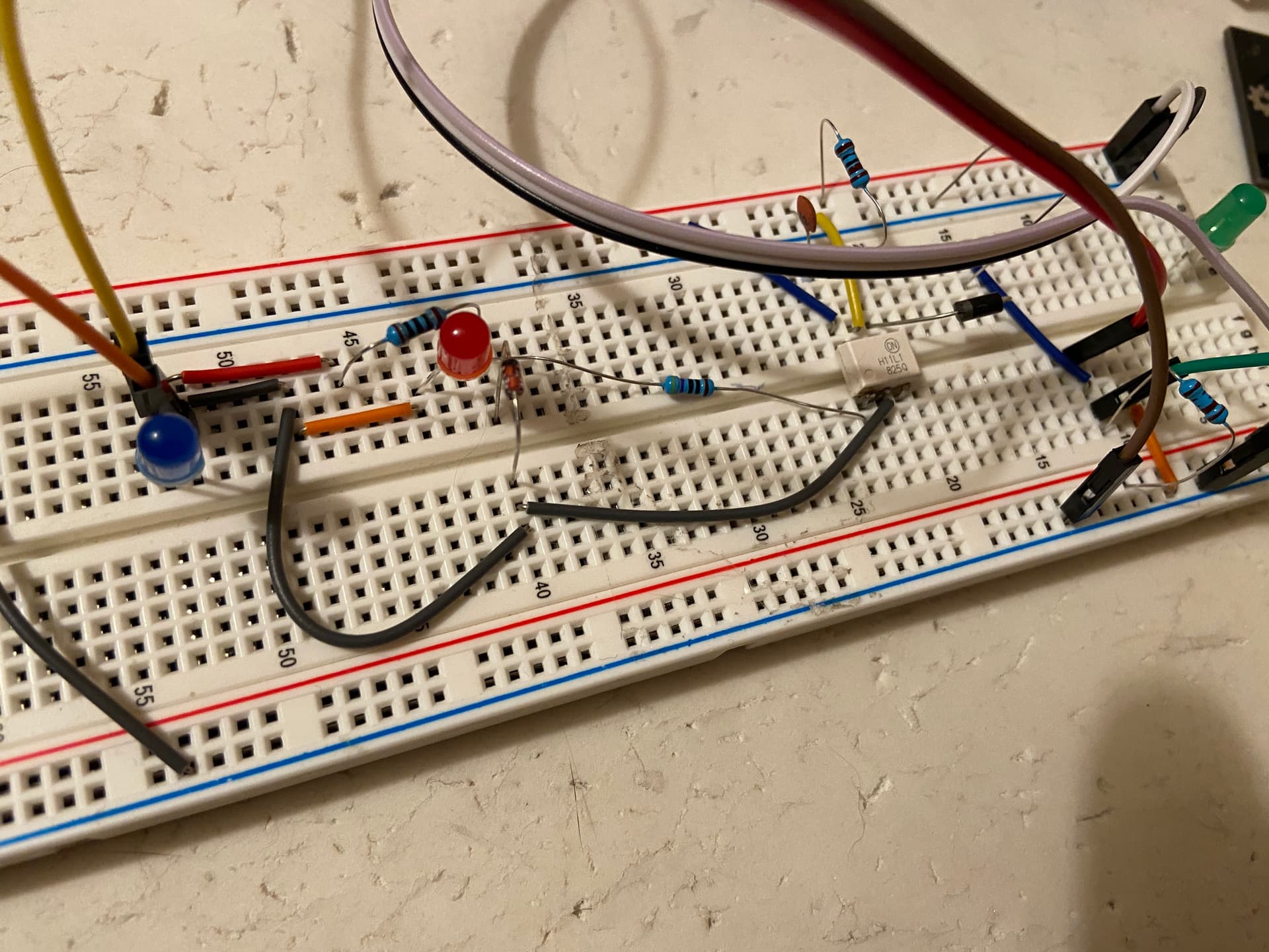
I removed the h11l1 to a breadboard and debugged the circuit there.
These h11l1s are indeed a pain to desolder but I managed to salvage it.
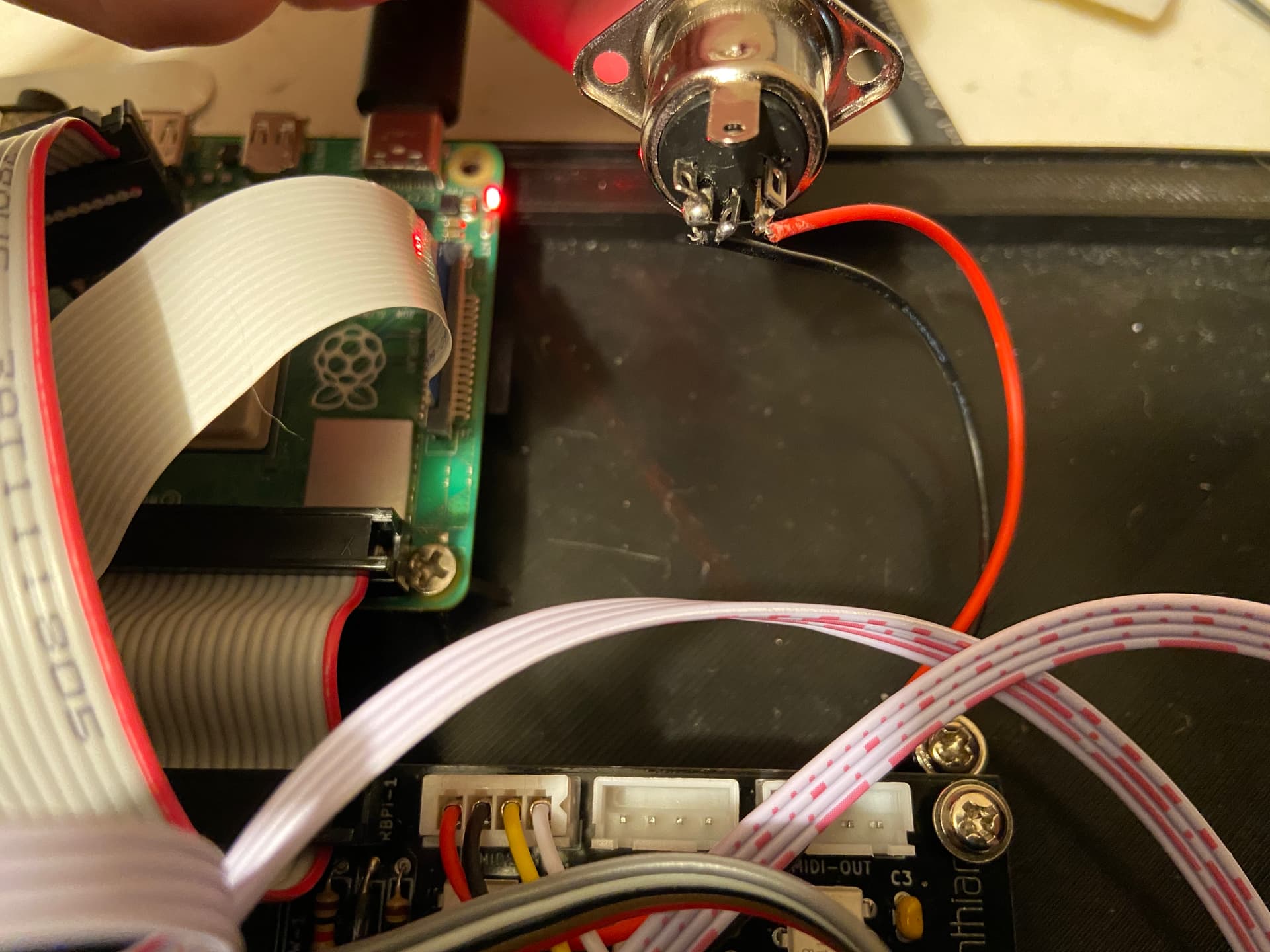
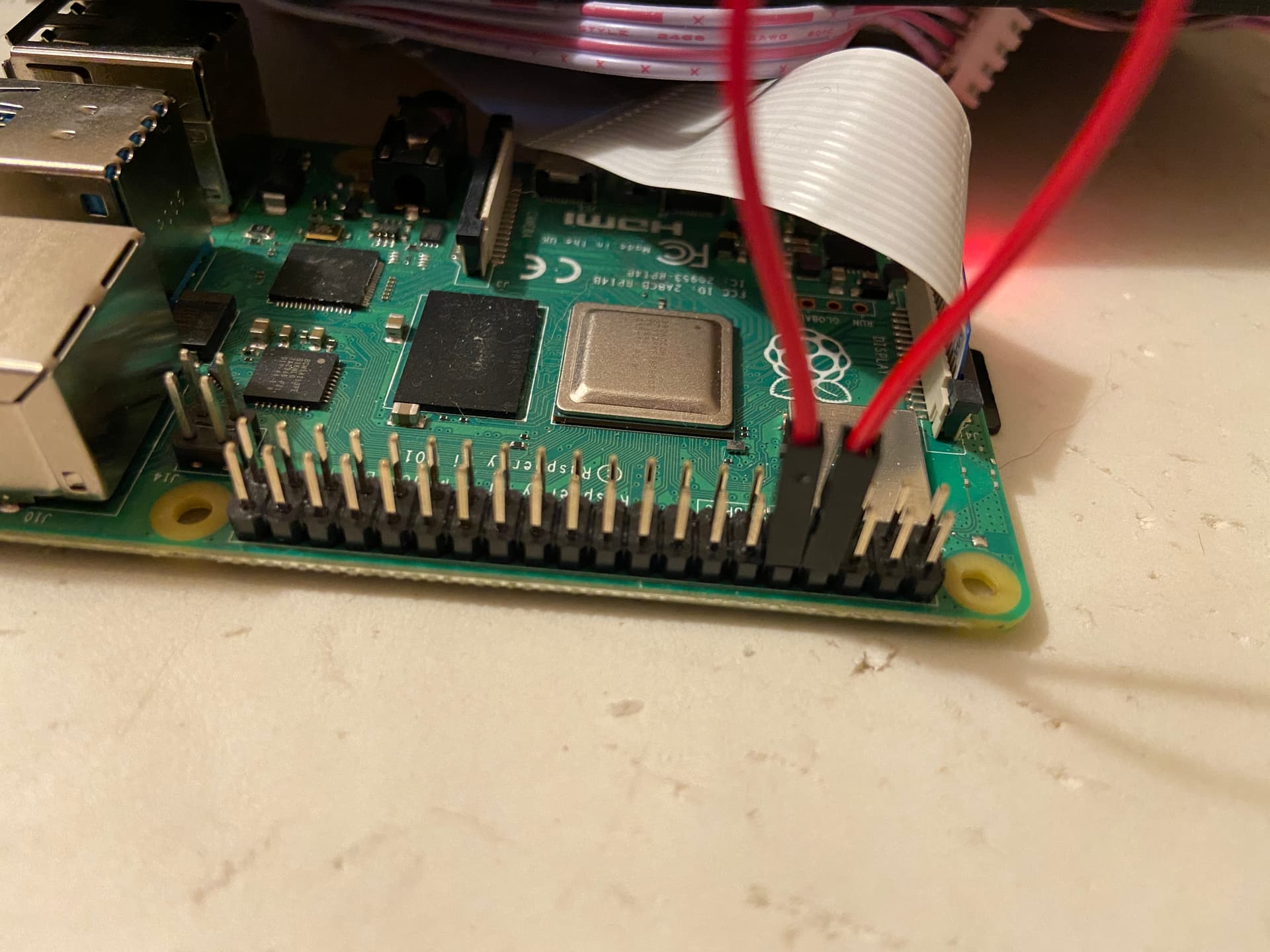
After much headbanging and learning about optocouplers it turns out that it was an issue with the RX pin in my Raspberry Pi 4.
To find this out I created a loop between the RX and TX pins and used the gpio utility while logged in to the zynthian by ssh.
Have a look at the gpio documentation:
http://wiringpi.com/the-gpio-utility/
Because it uses the Wiring Pin pin numbers that may differ from the physical numbering you may be used to.
Basically what we do is send and receive values using the TX and RX pins in our Raspberry Pi, without any additional circuitry involved.
Set pin 15 (TX) to output:
gpio mode 15 out
Set pin 16 (RX) to input:
gpio mode 16 in
You can see the value in the RX pi with the read option:
gpio read 16
And you can write a 0 or a 1 to the TX pin with the write option:
gpio write 15 1
Then when reading from pin 16 (RX) the value must match what we have written in pin 15 (TX):
gpio read 16
1
Verify that when we write a 1 to pin 15 we read a 1 in pin 16, and when we write a 0 to pin 15 we read a 0 in pin 16.
If the value read from pin 16 does not change with the values we write to pin 15 then we know that there’s something wrong with either the TX or the RX pins in the Raspberry.
In my case I have just replaced the Raspberry and MIDI in works!
I hope this can be helpful to someone else in my predicament.
If this was to happen to me again I would first verify that RX and TX pins are ok. It’s very quick to test and it would have saved me several hours. It makes sense that I may have inadvertently fed more than 3.3V in these during my experimenting and tweaking with the circuits.