I’m at a loss, I can’t get buttons or encoders responding at all through the chip ![]()
They work ok direct to the pi GPIO
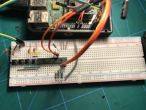
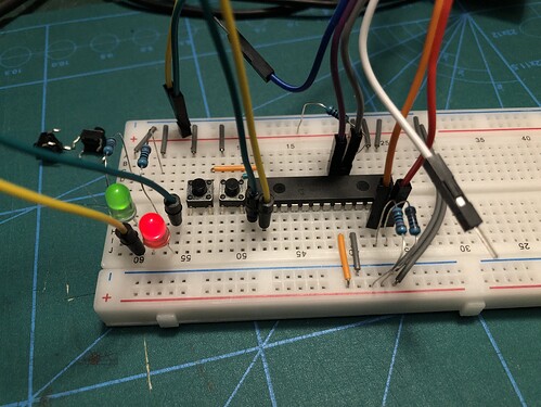
I have all the connections in the pic, I added some capacitors also. Can anyone see if there’s something wrong here?
Is it possible the chip could detect but actually be defective?
Those capacitors are doing nothing. Both pins are connected together. They need to go across the switch pins. Turn them all through 90 degrees.
Thanks, I’ve done it. I’d never used a breadboard til a few weeks ago so I’m finding a bit of a learning curve with this electronics stuff. So I’m setup for debounce (once it actually works).
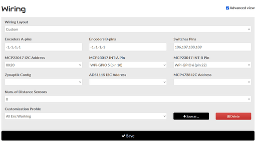
One thing I noticed today that was strange, I was getting errors in the UI log until I only set the switches to MCP pins on side A (100,101…107) etc. If I try and put anything on side B I get a constant steam of errors in the log. I tried shifting the interrupt on side B to another GPIO but that didn’t make a difference either.
This thing hates me, I can plug in leds and get them going with the i2cset command (side A or B) but zynthian refuses to respond to the buttons.
I have a pi5 that I’ve been meaning to setup, maybe it will work better there…here goes
If you are able to drive LEDs directly from code, can you also check that you can read switches using similar code?
I’m not exactly sure of how to read the exact pin using i2cget. Combined with the ‘wait’ command I have input a bunch of numbers that respond with a fixed number 0x00 an not affected by button presses(or hold). This one gives a stream of different numbers but still not certain it’s actually affected by the button presses:
watch -n 0.1 i2cget -y 1 0x20 0x11
With more attempts I could see 0x12 & 0x13 do the same.


