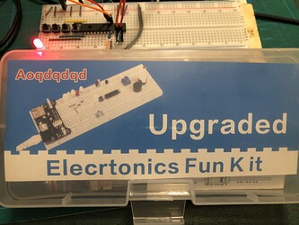
Troubleshooting config for MCP23017 on breadboard

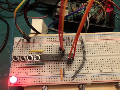
I’ve been trying to get this chip configured on the breadboard prior to setting up a larger number buttons in a case. The encoders are there too but I want to get the buttons going first before I try other connections through mcp23017.

So far I can get the chip recognised in webconf but cannot get any response from the row of buttons. I’m not sure which wiring is right (i tried flipping wiring connections on 2 of 4 buttons to see if it made a difference but no luck). I entered all the numbers in webconf in the hope it would pick up at least one of them.

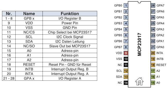
Can anyone take a look and see if I’m missing something? One thing I don’t understand very clearly is the interrupts settings. I’ve wired a couple of connections to the pi according to the chip diagram shown (connecting pin 11 & 13 on pi to pin 19 & 20 on the chip).

image

MCP23017_Pinout

It looks like you are missing pullup resistors on the I2C pins.

[Edit] I think you need encoder pin configuration, even if it is -1,-1,-1,-1.

Is that really all that would prevent them from working though? Previously when I wired the encoders directly to the GPIO on the pi they would work (though not reliably).

When I add 10k resistors between the wires and pins, the chip no longer detects.

It would be helpful if you did another pic with the pull-up resistors in place so we can see if they are correctly placed.

Sure, maybe I don’t have something right still.

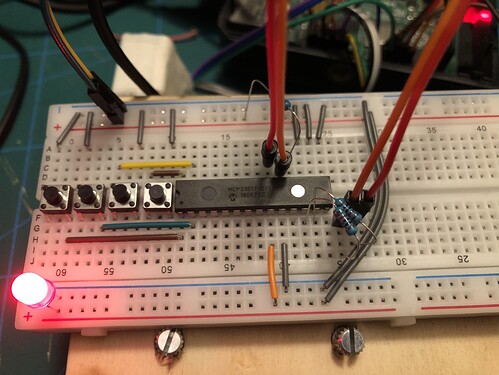
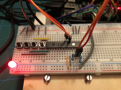
No - that is not right. You want your I2C wires to go directly from the RPi to the MCP pins. You also want resistors from each of the MCP pins to +V. It looks like you have put the resistors in series with the I2C wires.

on SDA and SCL only

The chip remains detected now which is an improvement.

Is there something else I’ve got wrong with the button wiring or in webconf? I changed all the encoder fields to -1.


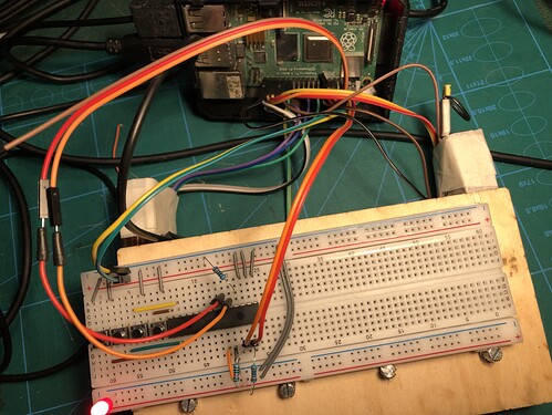
Edit: another pic for context, hard to see the connections on the pi though. All the additional wires are going to the encoders underneath.

It looks like you have the switch connected to +V. If the MCP is using internal pull-up (as I believe it does) then you need to connect the switches between 0V (GND) and the MCP input pins.

[Edit] Sorry - on closer inspection I see they are connected to GND.

My sympathy’s lie with that poor LED…

Whats the supply voltage on the MCP23017…?

Don’t be put off by this you are very close, and your breadboard interconnect wire trimming is magnificent.

Try it without the LED directly across the supply lines.

1 Like

I’m not sure I understand, the grey wires go to the negative at the top and the coloured ones go horizontal to the pins on the chip.

Is there some reference I can use about the numbers used in webconf (100,101 etc.)?

1 Like

100 is for GPA0, 101 for GPA1 and so on
108 for GPB0 …115 for GPB8

1 Like

So you have switches 106, 107, 108 & 109 connected.

I put everything on 3.3.v from the pi. The flat connectors are fiddly to remove but I really wanted to see the connections clearly for my sanity and also it makes hitting the buttons easier.

When I started looking to buy resistors and saw Elecrtonics Fun Kit, I couldn’t refuse. Now sometimes it’s a fun kit but lately with this chip it’s been more Fu%& It!!

Am I being mean to the LED? Sorry little guy :sweat_smile:

I’ve updated webconf to only these numbers. I should probably write them down in the wiki.

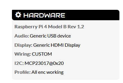
And moments later I have found the zynthian hardware page with a bit of useful info was orphaned so I added it to the ‘specific guides’ list. Zynthian Hardware - ZynthianWiki

Alas, no buttons working still. I’ll have to try again tomorrow.

LEDs or Light emitting Diodes to their close friends and colleagues.

The big trouble with them is they have a thermal characteristic which is the opposite of a resistor.
When a resistor warms up it’s resistance increases which means it will reduce current in a hot circuit. This is a good facility.

LED’s are the opposite as they warm up they take more current which means that there is a serious possibility ( from the LED’s perspective) that the current will increase as the temperature goes up, which will increase the heat, which will . . .

Phut.

So how do we stop this?
Well we try to limit the current that can flow in to the LED and keep it below a sensible threshold. In short a resistor of some value…

Whcih brings us to another fact about LED’s and ohm’s law.

The fact about LED’s is that they have a voltage which can be measured across the terminals and like a zener diode or the perpetual 0.6V across a silicon diode or the 0.25V across a germanium or a shottky diode, there is a voltage that the LED runs at, pretty much irrespective of the current flowing though it, until of course it goes . . .

Phut…

And this is the hint towards the value of resistor we need.

So we have a 3.3V supply and a red led ( 2.5 volts roughly)

3.3 Volts - 2.5 Volts = 0.8 Volts

An LED data sheet.

So how much current, or to put it another way how bright is the LED. to be?

Well the data sheets says the LED will do 20mA continuously but it’s just being used to indicate the presence of power so it doesn’t need to burn holes in things so start at say 1mA just to see how bright it is …

V = I R

0.8V = 0.01A * R

About 80 Ohms…

So a 80 ohm resistor or similar will perform the function.

This does two things. It keeps the current going through the LED limited, which is of interest to the LED, but as you have it wired the Forward voltage of LED acts like a zener diode and clamps the voltage across it to, well in the case of this Datasheet, 2.5V which is probably a bit marginal for the MCP23017. Put the LED in series with the 80 Ohm resistor and the LED and the MCP23017 can each comfortably run at the voltage they want to, with any current flowing between them will be limited by the resistor and the V = IR solution.

Basically if dealing with LED’s there will be current limiting resistor somewhere around to limit the volt drop from the supply it’s connected to . . . . .
Just for reference the Blue Pill STM32 Board uses 3.3Volts and 510R resistors, so it looks like one can go considerably lower current . . .

Hope this helps. I just happened to be reading about laser diodes this morning and that’s where the temperature comp stuff comes from . . .

Course if you really want temperature stability, who wants to describe multi VCO temperature ovens…?
2 Likes

The current limiting resistor has very little to do with the temperature of the LED for regular LEDs.

A good starting value is anywhere from a few hundred to six hundred ohms, then adjust, or don’t bother to taste - the lower you make the resistor the brighter the LED will be.

agreed, But it is a demonstrable effect. Strap two LEDs together and heat one, it will get brighter rather than the opposite effect if you try it with two resistors. . It is a factor that can be considered and it’s a useful insight into semiconductor behaviour.
I’m looking at running a laser diode for possibly years for a bell related project and the power supply design to prevent thermal run away and protect the life of the diode is becoming a considerable design endevour…

It tends to almost be a personnal choice. I always used 1K resistors on TTL 5.1V’s which dates back to a digital sequencer built in Nov 1977 - the PE 128 Note Sequencer. or there abouts…

2 Likes

image

1 Like

I’ve taken the LED out (for good luck?) but still not able to get the buttons working through the chip. I’ve ripped all the old connections to encoders out of the pi and tried the buttons directly to GPIO and they work ok. When I try and run through the chip it doesn’t work again.

I might actually be getting closer now. One thing I’ve noticed is when I pull the SDA data cable out it makes the UI go rapid fire through a bunch of screens and sometimes it appears to get stuck on a blank grey screen. When I shuffle the cable around, it seems to go back to ui screen again.

So it appears to be doing something but just not via the buttons.

I tried again and now it’s like endless button presses flying through the menus, I can’t stop it even after unplugging the breadboard from the pi.

I’ll try again tomorrow