First time builder here. I’ve successfully built a Zynthian using a Raspberry Pi 3B+, Raspberry Pi compatible DAC hat and a Ozzmaker 3.5 screen. I’m currently in the middle of trying to make custom encoders using parts I bought off ebay. The MCP23017 I managed to get hooked up and communicating to the Raspberry Pi however my encoders aren’t working as they should. The encoders I’m using where soldered onto a PCB that had 4 pinouts. The pinouts where GND, VCC, GA and GB. Im assuming that GND goes to ground on the MCP23017, VCC goes to the switch pins and GA and GB go to encoder pins A&B. However, this doesn’t seem to be the case and I have no idea whats happening or how to set custom pins on the Zynthian set up page.
Any and all help would be greatly appreciated and yes! I’m planning on writing up a build log especially for other aussies looking to locally as many parts as possible.
Hi @astrosloth123. Welcome to Zynthland. I hope your journey will be enjoyable.
VCC is a supply voltage label and is probable used to bias the encoder switches via pull-up resistors so should go to 3.3V. Ground goes to ground and is used as a common switching level / pulse. GA & GB are your two encoder switch pins A & B. With those wired and configured in webconf you should get rotary encoders working. You haven’t mentioned any other pins so your encoders may not have push switches or maybe they are not presented on a connector. Post some pictures of your encoders and a link to where you bought them.
As someone recently said here, “ground is ground, except when it isn’t”! Within a standard (and most custom) Zynthians there is one common ground used for all digital and analogue signals so you can daisy chain or star wire a single ground connection to all points that need it.
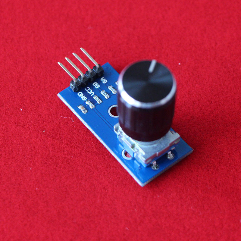
It looks like the encoder module does not have it’s switch presented on the connector which is kinda contrary to the eBay description. Check that there is a definite click when you press lightly which would indicate the shaft does have a switch. Also, if it has three pins on one side and two on the other this suggests a switch. (Three pins are encoder A & B plus common (ground) in the centre). Two pins are the switch with one pin usually connected to common (ground).) I can’t see from the stock image the PCB traces so can’t tell what is connected. You could solder wires to the switch pins. If one is already connected to ground via PCB then you just need the one wire to the other pin.