Using Hifiberry Digi+ with all-in-one module

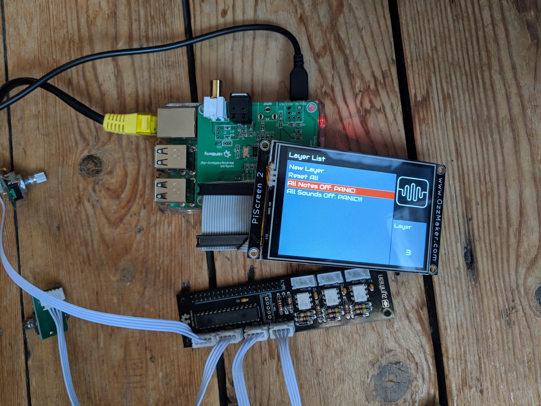
I am trying to build a zynthian using all the same items in the V2 kit, but instead of using the Hifiberry DAC+ I would like to use my Hifiberry Digi+ so that I have digital audio out.

The Pi won’t boot when everything is connected. I think that the Hifiberry Digi+ might be using the same GPIO pins as the all in one module.

Outdated info... see post below

According to Hifiberry, the Digi uses the following pins:
GPIO 2-3 - used for configuration
GPIOs 28-31 - used for the sound interface
https://www.hifiberry.com/build/documentation/gpio-usage-of-hifiberry-boards/

Can anyone suggest how I might make this work? I am thinking that if I can configure the software to use alternate pins then I can make a custom cable to attach the module to the Pi.

Many thanks!

Continuing my attempts to get this working…

First of all I’ve tested that everything works WITHOUT the Digi+

Also I’ve tested that everything works WITHOUT the All In One module

For good luck, I also tested the ribbon cable.


According to Hifiberry, these are the pins that the Digi+ uses:

GPIO (Pin)
2    (3) - Hifiberry Digi+ [1]
3    (5) - Hifiberry Digi+ [1]
5    (29) - Hifiberry Digi+
6    (31) - Hifiberry Digi+
16   (36) - Hifiberry Digi+ [2]

Info from GPIO usage of HiFiBerry boards | HiFiBerry
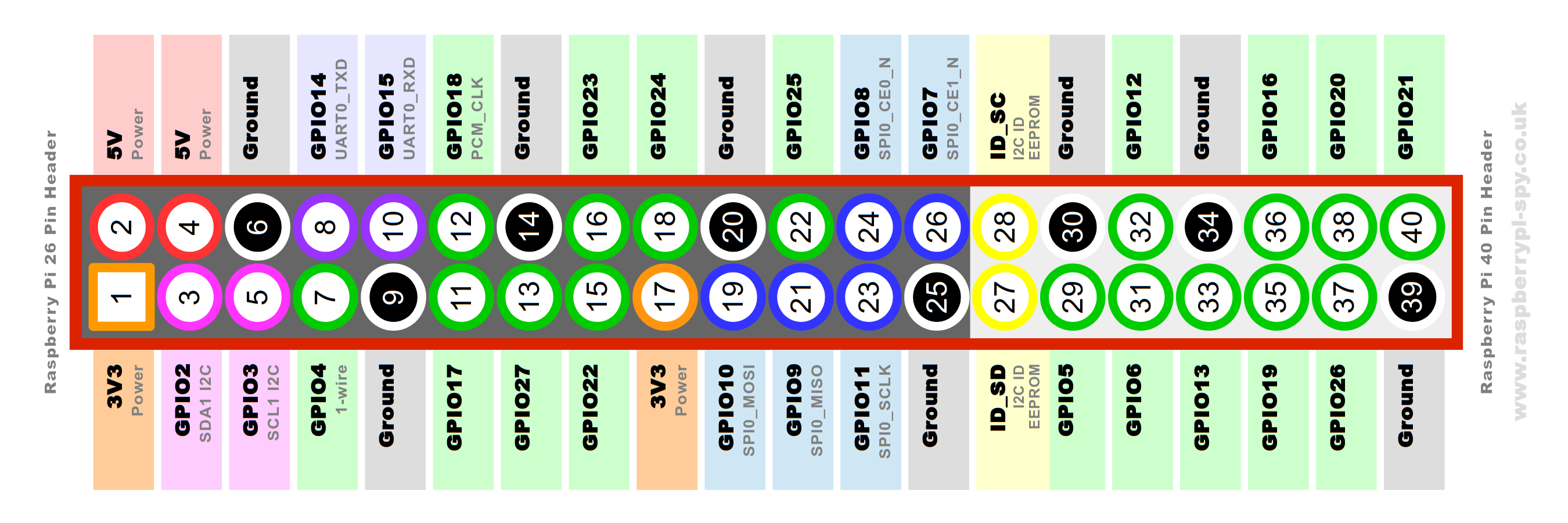
[1] “GPIO2-3 (pins 3 and 5) are used by our products for configuration. If you are experienced with I2C, you might add other slave devices. If you a a novice, we don’t recommend this at all.”
[2] “On the HiFiBerry Digi+, GPIO16 is also reserved.”

From the All in One module schematic ( SVG Picture created as zynthian_allinone.sch.svg date 2018/09/10 12:17:32 ) I can see that PIN 36 (GPIO 27) is being used as Interrupt Pin A. If this is the reason my Pi won’t boot, I will have to try to use a different pin.


My plan currently is:

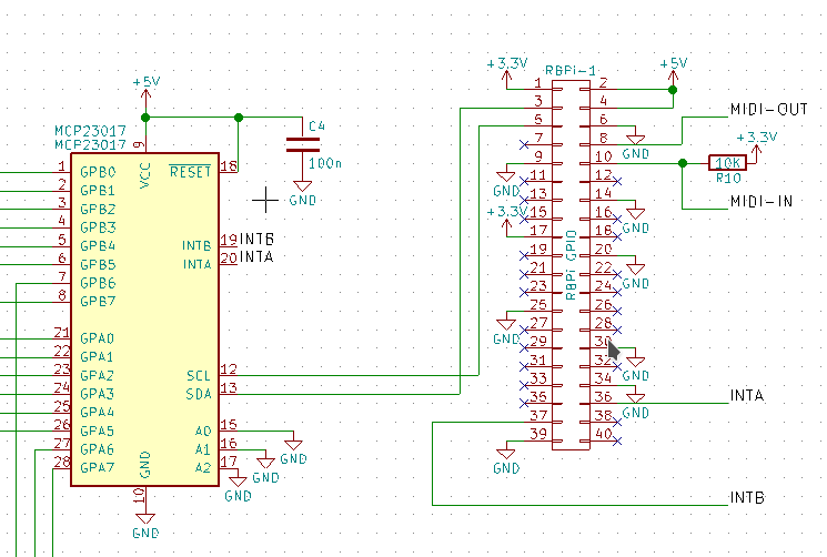
  1. Fork zyncoder and change the Pin definition on line 44 of zyncoder/zyncoder.c to a free pin - maybe 35 (GPIO 19) as I don’t think the screen uses this
  2. Make a different cable which connects PIN 35 on the Digi+ to PIN 36 on the module, and doesn’t connect PIN 36 on the Digi+ to anything

Pins 30 and 34 are Ground and on the schematic seem to be connected to Pin 36. I will have to try to understand this and how this would affect using a different pin.

If anyone has any ideas, let me know :slight_smile:

Hi Joseph @Fitz

perhaps there is a address conflict on the I2C bus?

Hifiberry says for the Digi+:
GPIO2-3 (pins 3 and 5) are used by our products for configuration. If you are experienced with I2C, you might add other slave devices. If you a a novice, we don’t recommend this at all.

This is not a problem as long as you don’t have an address conflict on the I2C bus. The MCP23017 on the AllInOne board seems to have 0x20 as address. I don’t know what address the Digi+ has. But you can try by starting without AllInOne and connect via ssh to your Raspberry. Then start i2cdetect -y 1 as root. If it reports also the 0x20 as address you have a problem. To solve it you have to solder a little bit (to give the MCP23017 a new address) and manipulate zyncoder.c (line 118).

But first let’s see if this maybe the problem.

Regards, Holger

1 Like

If this is the case, we need to refactor the zyncoder and let the webconf provide the data.

@mheidt You will always have the problem to additionally setup the address (in hardware) on the AllInOne. Jumpers are needed for selecting the I2C address of the MCP23017. Perhaps a good idea for the next PCB revision/production.

Good news on the I2C bus, looks like the Hifiberry Digi+ uses cx30

Full output from `i2cdetect -y 1`

For comparison: Pi with All in One Module

 0  1  2  3  4  5  6  7  8  9  a  b  c  d  e  f
00:          -- -- -- -- -- -- -- -- -- -- -- -- --
10: -- -- -- -- -- -- -- -- -- -- -- -- -- -- -- --
20: 20 -- -- -- -- -- -- -- -- -- -- -- -- -- -- --
30: -- -- -- -- -- -- -- -- -- -- -- -- -- -- -- --
40: -- -- -- -- -- -- -- -- -- -- -- -- -- -- -- --
50: -- -- -- -- -- -- -- -- -- -- -- -- -- -- -- --
60: -- -- -- -- -- -- -- -- -- -- -- -- -- -- -- --
70: -- -- -- -- -- -- -- --

For comparision: Pi with Hifiberry Digi+

 0  1  2  3  4  5  6  7  8  9  a  b  c  d  e  f
00:          -- -- -- -- -- -- -- -- -- -- -- -- --
10: -- -- -- -- -- -- -- -- -- -- -- -- -- -- -- --
20: -- -- -- -- -- -- -- -- -- -- -- -- -- -- -- --
30: -- -- -- -- -- -- -- -- -- -- -- 3b -- -- -- --
40: -- -- -- -- -- -- -- -- -- -- -- -- -- -- -- --
50: -- -- -- -- -- -- -- -- -- -- -- -- -- -- -- --
60: -- -- -- -- -- -- -- -- -- -- -- -- -- -- -- --
70: -- -- -- -- -- -- -- --

Ok… good news. Have to think about this. AFAIK GPIO 16 should be “free”… strange.

@C0d3man Thanks very much!

Here’s what happens when everything is connected… nothing!

Red LED on with no activity on the green LED on the Pi.

Sorry, forget my last comment (i deleted it). I was using the WiringPi GPIO numbering convention, and it’s not the RBPi official convention, used by HifiBerry.

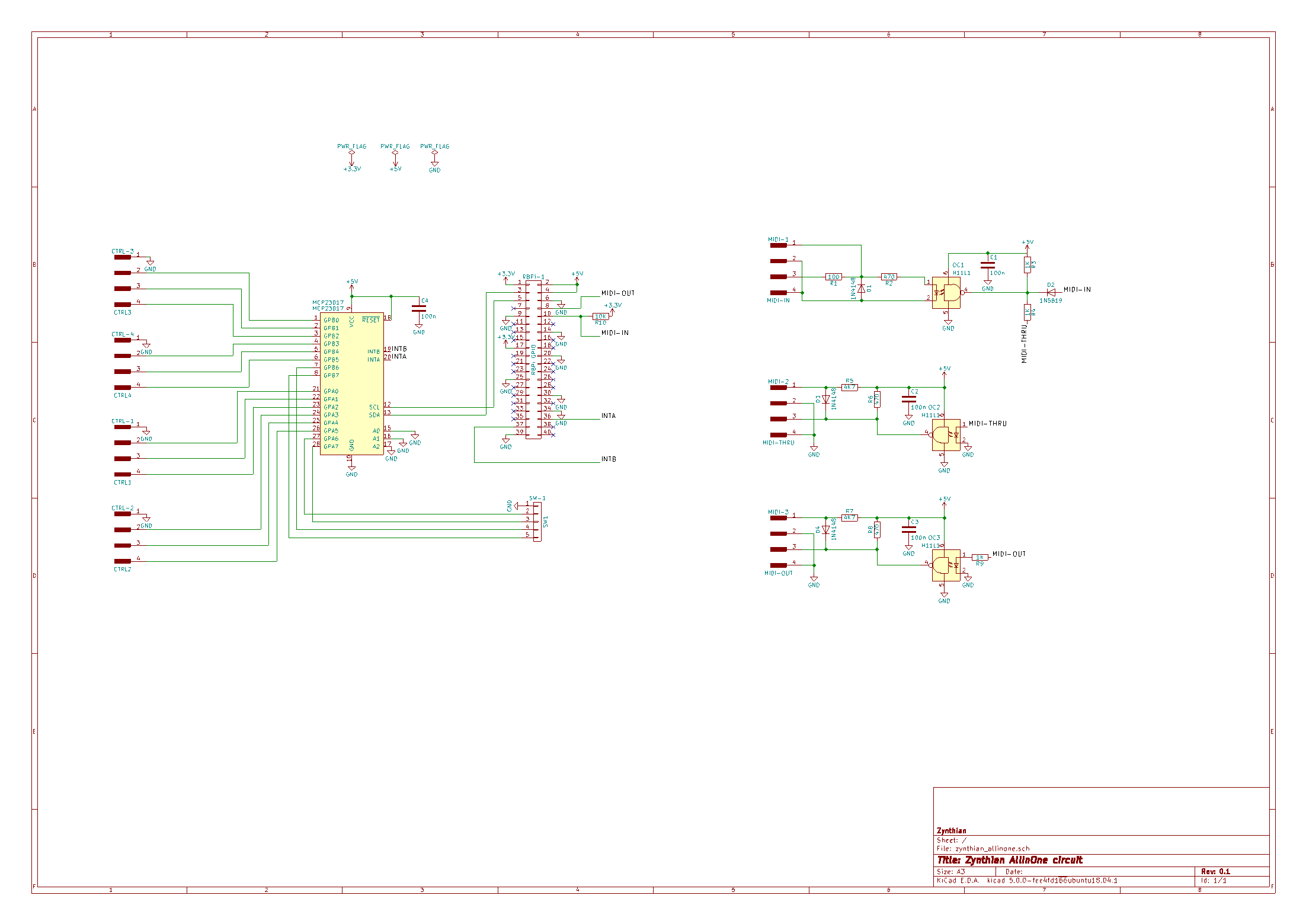
So you are right, the GPIO 16 is pin 36, used by the AllInOne circuit for MCP23017 interrupt A. This is a problem. In the next hardware revision i will add a “jumper” configuration, so you can choose a different pair of pins. Of course, you will have one for free, although i can’t tell you a date, i hope it will be not too late :wink:

Regarding the code, i will do the modifications for allowing the configuration of interrupt pins from the webconf.

Kind Regards,

I was totally confused by the pins and GPIOs too. In the code the pin numbers are used (WiringPi convention?), everywhere else refers to the GPIO numbers.

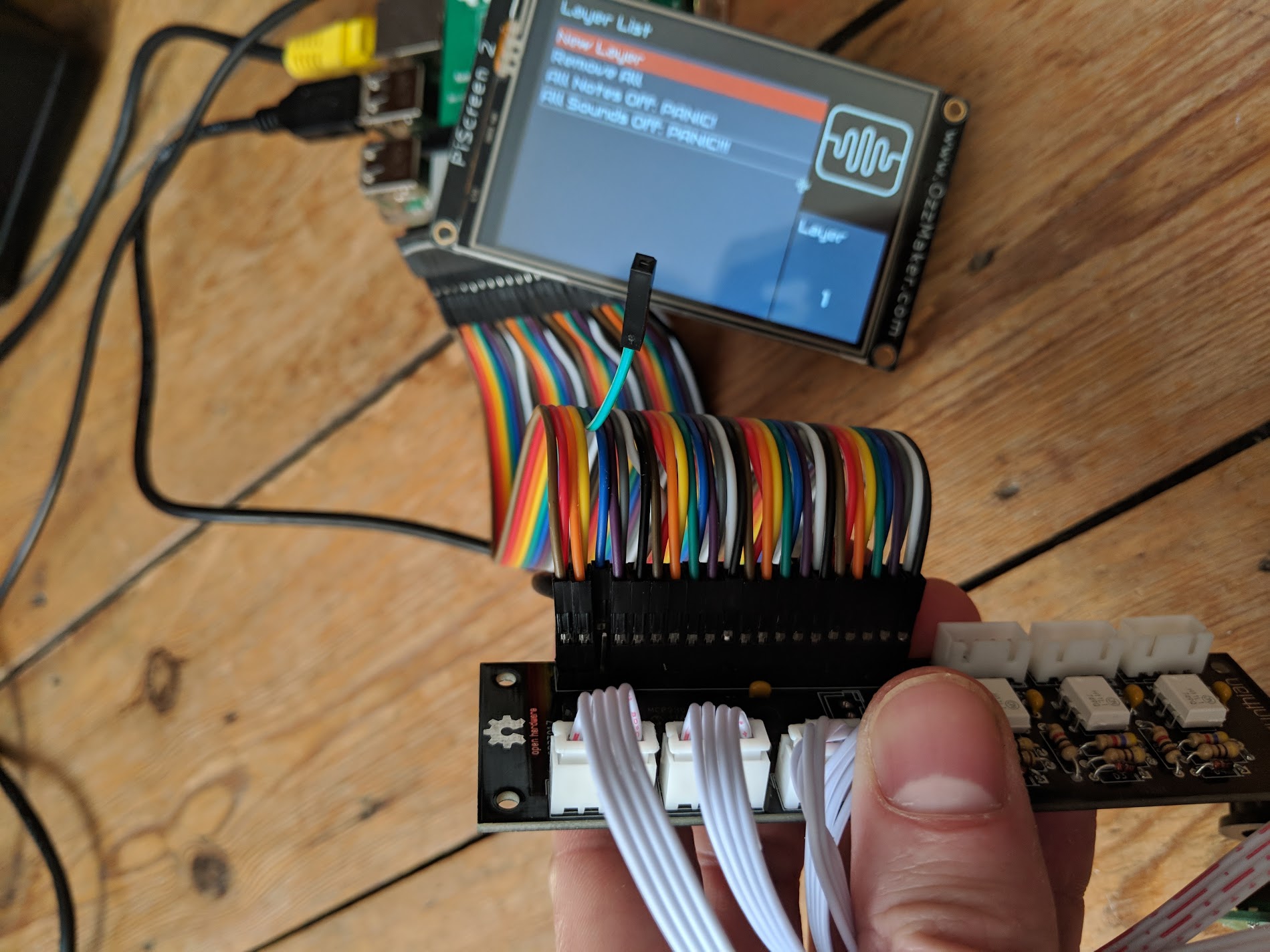
I have some breadboard wires so I will attempt to connect to another pin and change the code and see if I can get it booting.

If you need me to test anything let me know!

Yes, zynthian code uses WiringPi GPIO numbering convention because we use this library for interfacing GPIO. It’s a mess to have 2 conventions … in the next refactoring i should change this.

@Fitz

Hm - I took a look at the schematics and saw that the GPIO16 is used as INT_A for the MCP23017:

So you have to “move” the pin 36 to (perhaps) 35 or 38 AND you have to recompile zyncoder with some changes (where to find INT_A))…

I am not 100% sure if this is the solution, but this seems currently to be problematic.

Regards, Holger

@jofemodo

The following schematic says that GPIO15 is the UART_RX:

https://www.raspberrypi-spy.co.uk/wp-content/uploads/2012/06/Raspberry-Pi-GPIO-Layout-Model-B-Plus-rotated-2700x900.png

GPIO16 is used as INT_A for MCP23017 - or am I wrong???

More testing…

You’re right @jofemodo. Disconnecting GPIO16 (PIN 36) allows the Pi to boot.
Now I’ll see if I can change the code to a use a different GPIO…

@Fitz

Try to use pin 35 and change line 44 of zyncoder.h from 27 to 24…

@C0d3man Great advice. I recompiled zyncoder with the new pin number (in zyncoder.c)

Good news: everything boots and the rotary switches control the Zynthian interface. Whoooop!

Bad news: There’s some very strong distortion on the digital audio out from the Digi+ with this connection. Listen here:

Could be something isn’t grounded? Which pins are essential for the controllers on the all in one module? I can try removing some more pins.

I hear the distortion through both the optical and the coax digital audio outputs.

I just created a PNG of the schematics for the AllInOne board:

you may need the follwing pins on the GPIO-connector of the Raspi:

1-6,8-10,(14),(17),(20),(25),(30),(34),36,37,(39)

The pins in round braces are redundant pins for 5V,3.3V,GND. Perhaps you don’t need them all…

HtH, Holger

deleted Just read your reply. Thanks! :upside_down_face:

I’ve added 2 envars for configuring the MCP23017 interrupt pins:

  • ZYNTHIAN_WIRING_MCP23017_INTA_PIN
  • ZYNTHIAN_WIRING_MCP23017_INTB_PIN

It should be added to the zynthian config file:

/zynthian/config/zynthian_envars.sh

@mheidt, could you add it to the webconf wiring tab?

Kind Regards,